NFPA 37 establishes the minimum fire safety requirements for stationary combustion engine installation and use
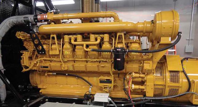
Combustion engines and gas turbines are widespread, essential components in buildings for supporting applications such as on-site power generation. Yet they are, by their nature, a fire hazard. Combustion itself means the process of burning. These devices often operate using liquid or gaseous fuels. A fire caused by one of these engines and turbines could have dire results.
That’s why NFPA 37: Standard for the Installation and Use of Stationary Combustion Engines and Gas Turbines is so important. It establishes the minimum fire safety requirements pertaining to the installation and operation of stationary engines and turbines. The standard is also applicable to semi-permanent installations such as portable engines and roll-up generators that are in service for a duration of one week or more.
The standard broadly focuses on the following facets:
- Engine locations.
- Fuel supply and storage.
- Lubrication systems.
- Engine flue exhaust systems.
- Controls and Instrumentation.
- Operations and maintenance
- Fire protection.
The origin of NFPA 37 dates to 1904 when the National Board of Fire Underwriters initiated the ”Rules and Requirements for the Construction and Installation of Gas and Gasolene Engines.” Editions of NBFU No. 37 were subsequently published in 1905 and 1910. The responsibility for the project was turned over to NFPA Committee on Explosives and Combustibles and in 1915 they published NFPA 37-37A: Installation and Use of Internal Combustion Engines (gas, gasolene, kerosene, fuel oil) and Coal Gas Producers (pressure and suction systems).
The responsibility for the standard was internally transferred to Committee of Gases and later to Committee on Internal Combustion Engines, which eliminated the provisions of coal gas. NFPA 37 has since been revised multiple times, and the latest edition is 2018.
The standard applies to new installations and modified portions of existing infrastructure. There are notable requirements of NFPA 37 as they apply to reciprocating engines that are frequently overlooked during design, construction, operation and maintenance. It is important to remember that the authority having jurisdiction and building insurance underwriters such as FM Global could enforce additional or stringent requirement so due diligence is critical to ensure compliance.
Engine location
A key requirement of the standard is to ensure that engines are readily accessible for maintenance, repair and firefighting to help mitigate the inherent fire hazard. This is especially important if generators are located on the upper levels of a building. While it is difficult to quantify “readily accessible,” industry-accepted best practices should be incorporated at a minimum.
Project-specific application will influence the engine location. NFPA 37 does not dictate when engines need to be enclosed in rooms and other applicable codes and standards need to be referenced to make that determination.
If the engine is enclosed in a room, then NFPA 37 outlines the requirements for the installation. The common locations and key requirements are:
Engines located within structures: The fire resistance rating of interior walls, floors and ceilings of engines rooms needs to be minimum one hour. In the event the room is located on top floor of a structure, then it is permissible for the ceiling to be noncombustible or protected with an automatic fire suppression system.
Engines using Class I liquid fuels need to be located in rooms with exterior exposure with accessibility for fire- fighting operations (see Figure 1).
Engines located within dedicated detached structures: Detached structures need to be of noncombustible or fire-resistive construction and located a minimum of 5 feet from wall openings and a minimum of 5 feet from structures with combustible walls.
The minimum separation is not required if exposing wall of the detached structure or exposed wall of adjacent structure has a fire resistance rating of minimum one hour or the detached structure is protected by an automatic fire protection system.
Engines located on roofs or outdoors: Engines and weatherproof housing located on the roof of a structure or outdoors needs to be a minimum of 5 feet from wall openings and a minimum of 5 feet from structures with combustible walls. Reduced clearances are acceptable if all portions of the structure that are closer than 5 feet from engine enclosure have a fire resistance rating of minimum one hour. Reduced clearances are also acceptable if it can be demonstrated that fire within the housing will not ignite combustible structures and the underlying reasoning and methodology is reviewed and accepted by the AHJ.
If the engine is installed on a roof, then the surface beneath the engine and beyond the engine and containment dike needs to be noncombustible to a minimum distance of 12 inches.
Gaseous fuels for engines
Frequently used gaseous fuels for generators includes natural gas, propane and biogas. Liquified forms of gas such as liquified petroleum gas and liquified natural gas are also considered gaseous fuels. The service pressure of gaseous fuel dictates the standard that needs to be used for design: For pressure not exceeding 125 pounds per square inch gauge, the piping system needs to be installed in accordance with NFPA 54: National Fuel Gas Code.
For pressure exceeding 125 psig, the piping system needs to be installed in accordance with ANSI/ASME B31.3, Process Piping. LPG systems need to be installed in accordance with NFPA 58: Liquified Petroleum Gas Code.
NFPA 37 outlines the components that need to be incorporated in gas trains serving generators. At a minimum, the following components are required per engine (see Figure 2):
- Isolation valve.
- Pressure regulator if gas pressure needs to be reduced to meet the engine requirements.
- Two automatic safety shut-off valves.
- Leak test valve for each ASSV or alternate means of proving full closure.
- Low pressure limit control for engines with a 2.5 million Btu/hour full-load input or higher.
- High pressure limit control with manual reset capability for engines with a 2.5 million Btu/hour full-load input or higher.
- Vent valve or valve proving system if inlet gas pressure exceeds 2 psig.
- Flame arrestor if biogas is used as a fuel and there is possibility of oxygen in biogas.
- Gas filter or strainer.
- Any other components required by the engine manufacturer such as pressure relief valves.
For engines operating at gas pressures greater than 2 psig at the equipment isolation valve, one of the following components also needs to be incorporated:
- Vent valve between the two ASSVs that fails open without externally applied power and discharges outdoors.
- A minimum of one safety valve equipped with a switch to prove valve closing.
- Listed valve proving system to prove ASSVs at each startup or shutdown of the engine.
Some of the gas train components identified above are typically supplied by the engine manufacturer; coordination during design is essential to ensure compliance with the standard.
If the valve train incorporates gas pressure regulators, they need to vent outside the structure and minimum 5 feet away from openings. However, venting outside is not required for the following regulator technologies:
- Regulators that operate with gas pressure on both sides of the diaphragm.
- Full lock-up regulators.
- Listed regulators that incorporate vent-limiting devices.
- Regulators incorporating vent limiting system with orifice sized for 2.5 cubic feet per hour or less (natural gas).
In addition, relief valves need to be installed downstream of non full lock-up regulator when the gas pressure upstream of a regulator exceeds 0.5 psig.
If additional shut-off valves are provided in the gas train for maintenance purposes and they are locked open, the key needs to be secured in a well-marked accessible location near the valve. In addition, at least one manual shut-off valve needs to be provided in an accessible location outside the fire hazard area of the engine for safely disabling fuel supply in the event of an emergency.
For installations involving multiple engines, equipment isolation valves need to be located within the first takeoff or branch pipe serving the individual engine.
ASSVs for combustion engines need to capable of shutting off and disabling the fuel supply to the engine within two seconds of the engine stopping. They also need to be capable of failing close without externally applied power.
As identified before, a gas train needs to incorporate two ASSVs. However, if the gas pressure does not exceed 2 psig, one of the ASSVs can be replaced with one of the following devices that is capable of shutting off within two seconds of engine stopping:
- Carburation valve.
- Zero governor-type regulating valve.
- Auxiliary valve.
Overpressure protection needs to be provided if the gas train is subject to one of the following conditions:
- Inlet gas pressure exceeds both 2 psig and the pressure rating of downstream components.
- Failure of a single gas pressure regulator will result in inlet gas pressure exceeding the pressure rating of any downstream component.
Liquid fuels for engines
Frequently used liquid fuels for generators includes diesel and gasoline. Considering the inherent hazard associated with flammable liquids due to their low flash point temperature, fuel tanks containing Class I fuels such as gasoline need to be located underground or aboveground outside of structures.
For fuels other than Class I fuels, aggregate capacity of fuel tanks not installed within dedicated room cannot exceed 660 gallons. Tanks with aggregate capacity between 660 and 1,320 gallons need to be installed within dedicated room of minimum one-hour fire rating. Tanks with aggregate capacity exceeding 1,320 gallons need to be installed within dedicated rooms of minimum three-hour fire rating.
It is important to note that these requirements are also applicable to tanks constructed in accordance with UL 2080: Standard for Fire Resistant Tanks for Flammable and Combustible Liquids or UL 2085: Standard for Protected Aboveground Tanks for Flammable and Combustible Liquids.
Fuel tanks of any size are permitted within engine rooms or mechanical rooms if the rooms are designed in accordance with recognized practices and incorporate means such as fire detection, fire suppression and fire containment to limit the spread of fire. Ventilation of rooms needs to be provided to maintain concentration of vapors below 25% of lower flammability limit of fuel.
To allow periodic inspection and maintenance of fuel tanks, a minimum clearance of 15 inches needs to be maintained around each tank. To minimize risks associated with the fuel filling and transfer process, tanks served by pumps need to be equipped with overflow line, high-level alarm and high-level auto shut-off. The overflow piping needs to be routed to source tank or collection system and capacity of overflow piping needs to exceed the fuel supply capacity at the tank. Valves or traps are not permitted in the overflow piping.
Engine exhaust and safety
Engine flue exhaust systems needs to be designed and constructed to accommodate heat, corrosive environment (internal or external), internal pressure including potential for backfire and external forces such as snow, wind and seismic activity. In addition, drains need to be incorporated at low points of exhaust systems to allow for draining of condensates or water ingress.
Engines with an output of 10 hp or more need to be capable of being shut down at the engine and from a remote location in the event of an emergency.
Operating instructions
O&M instructions need to be located at readily accessible locations for use by the operators. The instructions need to include the following at a minimum:
- Detailed explanation of engine operation.
- Routine maintenance instructions.
- Detailed instructions for repairs.
- Pictorial parts list and numbers.
- Electrical drawings for wiring systems.
- Instructions on fire safety features of the engine.
In addition, emergency shutdown procedures need to be developed and provided for each engine. The emergency operating procedures need to be located at readily accessible locations. Fuel shut-off valves need to be clearly identified or locations need to be indicated diagrammatically and posted near the engines
Engine fire protection
Upon activation of the fire suppression system serving the engine installation, automatic fuel stop valves need to close and mechanical ventilation systems need to shut down unless the engines are for emergency use or constantly attended and O&M procedures are in place to direct operator action.
NFPA 37 has been with us for more than a century. Its requirements have undoubtedly helped buildings operate more safely. And that means businesses have a better chance to survive and thrive.