This quick reference offers a guide for fire pump electrical design
Learning Objectives
- Understand fire pump power sources and electrical requirements.
- Determine electrical equipment locations, and the various aspects that define these locations.
- Review NFPA 20 and 70, which provide guidance on fire pump equipment specifications.
Fire pump insights
- NFPA 70: National Electrical Code defines how power should be fed to fire pumps.
- Electrical connections are crucial to fire pump design.
This design guide is meant to provide code references and examples to help an electrical engineer determine basic criteria that must be met for the installation of a fire pump. This guide was developed from NFPA 20: Standard for the Installation of Stationary Pumps for Fire Protection (2019 edition) and NFPA 70: National Electrical Code Article 695 (2020 edition), and any information included is paraphrased. For complete definitions and information, see applicable code section. Please note: design could differ depending on jurisdiction requirements.
Electrical systems for fire pumps are governed specifically by NEC Article 695. This article includes all of requirements for normal and alternate sources of power for fire pumps. When having an alternate generator power source, it can be argued that it falls within the emergency branch in NEC Article 700 (from Informational Note), and by default under the life safety branch (which also points to NEC 700) when in a health care facility under NEC Article 517.

Determine fire pump power source
Coordinate with the fire protection engineer to determine pump requirements. The normal source must be in accordance with one of the following (NEC Article 695.3):

Determine reliability/alternate source
The normal source must be deemed reliable and able to carry the LRCs of the fire pump motor and the pressure maintenance pumps and the full load current (FLC) of the accessory equipment. If this isn’t met, an alternate source is needed.
A reliable source possesses the following characteristics, but is up to the authority having jurisdiction (AHJ) to determine (per NFPA 20: Standard for the Installation of Stationary Pumps for Fire Protection Article A9.3.2):
- Source power plant has not experienced shutdowns longer than 10 continuous hours in year before plan submittal.
- Power outages have not routinely been experienced in area of facility caused by failures in generation or transmission.
- Normal source is not supplied by overhead conductors outside facility.
- Disconnects are installed in accordance with NFPA 20 Article 9.2.2.
An alternate source of power must be one of these scenarios (NFPA 20 Article 9.3.4):
- On-Site Standby Generator (NEC Article 695.3(D)).
- One of the Individual Sources above where the power is independent of the normal source of power.
When one of the sources is a dedicated feeder derived from a utility service and separate from the normal source, the disconnecting means, OCPD and conductors are not required to meet NFPA 20 Article 9.2 and shall be permitted to be installed with NFPA 70 (NFPA 20 Article 9.3.6.1)
Protective devices cannot be installed on load side of the power transfer switch (NFPA 20 Article 9.3.6.2).

Receiving AHJ approval
The following are the steps that must be taken to receive approval from the AHJ:
- Need reliability report from the utility on multiple years of history.
- Written formal statement and saved in the project directory.
- Presented to the AHJ and client early in the project.
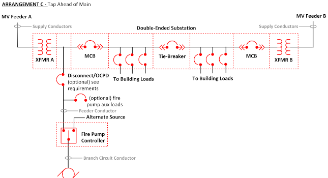
Electrical configurations
Preferred source arrangement examples are shown in Figures 2 and 3. Alternate source arrangement examples are shown in Arrangement A, and Arrangement B.
Jockey pumps are also known as a pressure-maintenance pump. These keep the pressure in the system at a constant level when fire pump is not in use. Note: Jockey pumps cannot be fed from downstream of the fire pump controller.
The jockey pump can be connected in multiple ways:
- Tap ahead of fire pump controller shown in Figures 2 and 3.
- From normal distribution source.
- From emergency or optional standby distribution source (but not required).
- Fire Pump Controller cannot be used to supply pressure maintenance pumps (NEC Article 695.6(I)).
- Refer to NEC Article 430.6.
- NEC Article 517 Equipment Branch.
Disconnect requirements
The best way to provide continuity of reliable power is a direct connection of the source to the fire pump control equipment. However, additional disconnects are permitted to create an electrically safe work condition and may be required by facility management.
The number of disconnecting means permitted are based on NEC Article 695.4(B)(1) and 695.5(B)].
| Single | Between the power source and:
Fire pump controller Fire pump transfer switch Combination fire pump controller and transfer switch Dedicated transformer |
| Additional | Multiple-Building Campus Style Arrangements |
| Where an On-Site Standby Generator is used to supply fire pump |
Note: For an individual normal feed, if there is an OCPD in the disconnecting means, it must be capable of carrying the LRC on the normal side.
To provide one disconnecting means before the fire pump, it must comply with NFPA 20 Article 9.2.3.1:
- Suitable for service equipment.
- Lockable in both closed and open position.
- Sufficiently remote from other building disconnects.
- Sufficiently remote from other fire pump disconnecting means.
- Marked “Fire Pump Disconnecting Means” in 1-inch letters.
- Placard next to fire pump controller stating where disconnect is located and location of key to unlock.
Note: “Sufficiently remote” is not defined by the NEC. How this is achieved needs to be acceptable to the AHJ.
Supervision in closed position by one of the following (NEC Article 695.4(B)(3)):
- Central station, proprietary or remote station device.
- Local signaling service that causes the sounding of an audible signal at a constantly attended point.
- Locking the disconnecting means in the closed positions.
Controllers shall be equipped with contacts (open or closed) to operate circuits for four conditions (NFPA 20 Article 10.4.8):
- Motor Running.
- Phase Loss (Power Loss).
- Monitoring is usually done by the fire alarm system. This is the easiest, but it does not have to be done this way.
- Phase Reversal.
- Controller or System Trouble.
When a transfer switch is used, two additional contacts are required for following conditions:
- Switch is in Emergency Position.
- Alternate Source Isolating Switch or Circuit Breaker is Open.
Note: Remember to coordinate short circuit current ratings for the controller and soft starter or variable frequency drive when tied to a generator.

Sizing fire pump equipment

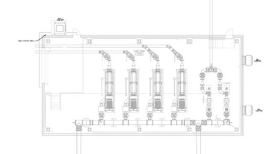
Determine fire pump equipment locations

Additional criteria
Starting voltage drop: Shall not be more than 15% at motor-starting conditions unless (NEC Article 695.7(A)):
- Successful start can be demonstrated on the standby generator system
- Bypass mode of a variable speed pressure limiting control with successful start on standby genset
Running voltage drop: Shall not drop more than 5% when motor is operating at 115% of the FLC rating (NEC Article 695.7(B)).
Note: Voltage drop can be calculated using an electrical software program, such as SKM System Analysis Inc., or done by default on generator vendor sizing programs.
Note: 15% needs to be maintained even when the generator is running, serving all other loads and then the fire pump is called to start.

Fire alarm requirements
Fire pump alarm and signals shall indicate (NFPA 20 Article 10.4.7.2):
- Pump or Motor Running.
- Loss of Phase.
- Phase Reversal.
- Controller Connected to Alternate Source.
- Alternate Source Isolating Switch or Circuit Breaker Open.
- Controller or System Trouble (ground-fault, pressure-sensing, variable speed trouble, fail-to-start).
Not allowed:
- Phase converters (NFPA 20 Article 9.1.7).
- Ground and Arc Fault Interruption (NFPA 20 Article 9.1.8).

Affiliated Engineers Inc. is a CFE Media content partner.