Presenters from the May 12, 2026, webcast, Advanced Motor Control Strategies for Water Pumping Applications: Maximizing Capital Efficiency, Energy Savings and Reliability, answer audience questions.
Presenters from the May 12, 2026, webcast, Advanced Motor Control Strategies for Water Pumping Applications: Maximizing Capital Efficiency, Energy Savings and Reliability, answer audience questions.

Motor control insights:
- Effective motor control selection requires balancing first cost, energy efficiency, reliability and lifecycle performance, with options such as synchronous transfer systems, bypass strategies and harmonic mitigation tailored to specific pumping applications.
- Engineers can improve pumping system performance by evaluating VFD control strategies, harmonic mitigation methods and backup generator compatibility to enhance efficiency, resilience and long-term operational reliability.
Learning objectives:
- Understand how synchronous transfer systems provide efficiency and reliability in multiple pump applications.
- Explore application considerations for system bypass requirements in pumping systems.
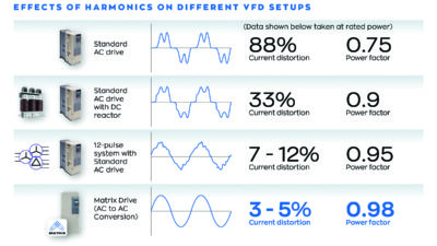
- Design strategies for harmonic mitigation when applying variable frequency drives: active front-end (AFE), multi-pulse converters and central harmonic correction units.
Designing pumping systems requires navigating a wide range of motor control options, each with implications for capital investment, operating efficiency, reliability and long-term performance.
Maggie Zhang, Lead Application Engineer, Ian Andrup, Product Manager, MVCA, and Steve Zipf, Associate Product Manager, all from Eaton, discussed practical, application-based motor control strategies for water and wastewater pumping systems using real-world examples and decision frameworks.
After the presentation, audience members had a chance to ask questions to the experts. Below are some highlights from the Q&A, covering topics like active harmonic filters, variable frequency drives (VFDs) and active energy control.
What is the preferred point of application for the active harmonic filters?
Active harmonic filters are mostly only available at low voltage. They are best applied in parallel with other harmonic generating loads in a MCC or other LV distribution point. Keep in mind the PCC and what you are trying to accomplish by mitigating harmonics (IEEE 519 or for general power quality improvement).
Is it possible to run multiple motors at reduced speed?
Yes, you can run multiple motors at reduced speed, but only if each motor is actively controlled by its own VFD or in a coordinated multi-drive system. In most standard single-VFD multi-motor setups, only one motor is speed-controlled, while the others run at full speed and are staged on or off. It really depends on the architecture you’re using.
Is it possible to start two motors at the same time and then start the other motors? Does the main VFD have the capacity to start more than one motor at the same time?
Yes, a VFD can start more than one motor at the same time if it is sized for the combined load — but that’s not how these systems are typically designed. In most multi-motor applications, the VFD starts motors sequentially to manage current and maximize capacity. Starting multiple motors at once would require a much larger drive and can make control less stable.
Are any of these harmonics reflected on the primary side of the utility transformer?
Harmonics can be reflected to the primary side of a transformer. However, the natural impedance of transformers tends to have a positive impact on harmonic mitigation. While it will slightly reduce THD, it will typically not be enough to stay within IEEE 519 guidelines.
What is the cost and footprint impact between 6, 12, and 18 pulse drives?
This is very dependent on the hp size of the drive. For low hp, moving to 12 or 18 pulse will represent a much higher relative percentage versus the 6 pulse drive cost. At higher hp (above 100 hp), it becomes much more economically feasible. For example, 12 pulse solutions are less common than 18 pulse because they do not guarantee IEEE 519 compliance, so 12 pulse drives often need other mitigation techniques. Because of this, financially it can make a lot of sense to move to 18 pulse.
Some water and wastewater plants will occasionally see flow demand ramping from 20% to 100% in a window of only a few minutes. Have you had any customers using these single VFD multi-motor lineups mention an issue with getting each pump up to speed in time?
We haven’t seen widespread issues reported with that, because these systems are designed to stage pumps in sequence as demand increases. However, the key is proper design and tuning. If the ramp is extremely fast or the system isn’t sized correctly, you could see some lag while additional pumps are brought online.
A general concern nowadays is harmonic distortion caused by data centers. Can this technology approach help to minimize this?
Yes, these approaches can be used in data center applications. Because harmonics are typically being generated by non-VFD loads, we typically recommend one of the system-level solutions for harmonic mitigation. Active harmonic filters are very common in this application, but passive filters could also see some use in this space.
Is it intended that this methodology is to only use the VFD for starting each individual motor, bringing it up to speed until all the motors are transitioned to “across the line” and no motors are run, other than when starting, on the VFD? Is this correct?
That’s correct for the synchronous transfer type architecture. The VFD is primarily used to start each motor and bring it up to speed, and then the motor is transferred across the line. Once everything is running, the VFD isn’t continuously controlling all the motors. That said, other system designs do keep at least one or more motors on the VFD for continuous speed control, so it really depends on the application and control strategy.
What if the transfer from the VFD to the utility does not happen?
If the transfer doesn’t happen, the motor can continue running on the VFD, so you don’t lose operation. The trade-off is that the VFD is tied up, which limits how quickly you can bring additional motors online. That’s why these systems often include bypass options or even a second VFD for redundancy — to make sure you are not relying on a single transfer event.
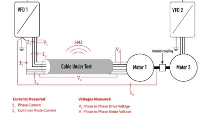
What are the cable requirements when the motor is located far away from the VFD?
At 4160, for an inverter duty motor, a dvdt is required at 150 ft, and a sine filter at 300 ft.
For the dual bus applications, since you are running it as a closed transition, are you rating the equipment at high short circuit current withstands?
The equipment will be rated for 50 kA, but the output of the VFD has a minimal impact on the available fault current.
Can we store dedicated settings for each motor-pump set in the VFD? The motors have different internal data and the pumps have different curves.
Yes, each individual motor will have dedicated profiles. Additionally, there will be an individual motor protection relay for each bypass contactor.
Are any special considerations needed when using AFE VFDs while on generator power? Does the AFE technology have any adverse effects on the generator?
Yes, the AFE drive can have some interaction with generator power due to the front-end filter that is commonly applied. Typically, AFE is more susceptible to voltage harmonics than an 18 pulse drive on generator power.
For active harmonic correction units, what is the benefit of the CT sensing? Where are these CTs typically installed? How is this handled in a retrofit application?
CT sensing for active harmonic filters is the most widely used method in the industry. Only select manufacturers have other sensing capabilities. The CT is typically installed at the transformer or feeder to the switchgear in question. You will want the CTs to be in a location where they will pick up all the downstream loads. In retrofit applications, you would want to wait for the next equipment shutdown to install CTs in the gear.
What happens with the active energy control below 30 Hz operation?
At low speeds (e.g., below ~30 Hz), active energy control is still active, but its impact is limited and more conservative to maintain stability.
For equipment with bypass, could you clarify if we need code-required back access?
Rear access is not required.
When we specify VFD starters, we normally use a standalone VFD instead of having a part of our MCC, because we can use what is available when we need replacement. Can Eaton’s VFD receive another manufacturer’s VFD?
Using feeders in an MCC to feed standalone VFDs is a very common practice in the industry. We have a selection of Eaton and some non-Eaton VFDs in our MCC offering. If others are needed, we can also leave space for field installation of equipment.
With sync transfer, is the VFD typically only used for starting or stopping? Or does it also get used to vary the speed of one motor?
Yes, the VFD can be used for continuous speed control.
MV motor control has two buses. Will this design increase MV MCC depth dimension?
The depth remains the same. The double bus is placed on top of each other and adds height above the motor starters.
What is the advantage of starting a motor using a VFD instead of a soft starter if the VFD is bypassed at the end?
A soft starter will still experience 2-3x FLA and is limited by the number of starts that it can do per hour. A VFD can completely reduce the inrush and can start multiple motors in succession.
Where are the VFDs manufactured, and what is the typical lead time for a VFD?
The VFDs are manufactured in Asheville, North Carolina. Lead times are 26 weeks.
Do you have a recommended approach to mitigate the existing genset harmonic distortion contribution due to impedance increase?
It sounds like this is an existing facility. In this case, the easiest solution would be adding an active harmonic filter. Depending on the load mix, number of VFDs, and age of VFDs, there may be other solutions to consider like 18 pulse VFD.
How does dynamic speed control influence pump efficiency when multiple pumps operate in parallel?
Dynamic speed control has a big impact on efficiency in parallel pump systems because it allows you to match flow directly to demand instead of relying on throttling. At partial load, even small reductions in speed can significantly reduce power consumption. It also enables better staging and load sharing between pumps, so the system can operate closer to its optimal efficiency point across the full operating range.
How would the sync transfer work on the slowdown side?
The VFD will sync with the utility and transfer the motor to the VFD, where it will provide a controlled soft stop.
What voltage range does this work for?
2300 V to 13.8 kV.
If we use 18 pulse drive VFD, do we need LC line control to suppress harmonics?
If 18 pulse VFDs are the only nonlinear loads in your system, they typically are IEEE 519 compliant so no further harmonic mitigation is usually required. If you have other nonlinear loads, then further correction may be needed.
Does the AEC feature require feedback from the motor?
No, active energy control doesn’t require any motor feedback devices. It is completely sensorless. It is built directly into the drive’s logic, and the drive uses its own electrical measurements to monitor load and adjust voltage to the lowest stable point.
How many motors can you run at once with this setup? What if you need to run at a reduced speed for some of the pumps?
The number of motors is limited by the bus amperage, which maxes out at 3000 A.
Sync transfer lineups require VFDs each rated for the capacity of the entire system, correct?
The VFDs can be either fully rated or rated for starting duty, which reduces the power of the VFD by 40-60%.
When mitigating harmonics of all the motors and drives, they are required to individually comply with 519. Is there an application where a single large filter can handle the downstream non-linear loads and reduce cost? I ask because I believe harmonic issues are a culmination of the system and not individual components.
It is important to understand that IEEE 519 is measured at the point of common coupling, not at the output of each VFD. Because of this, not all drives need to be within IEEE 519 compliance. You can have a system level solution to mitigate harmonics at a system level or implement low harmonic VFD solutions.
Regarding the active energy control, is this system using intelligent control (fuzzy logic)? Is there a concern for instability at the targeted load as the system dynamically looks for this target? Using a perturb/observe intelligent control system for something like an inverter may have this concern.
That’s a great question. Active energy control isn’t using fuzzy logic or a perturb/observe method. It is a deterministic, adaptive V/Hz control that gradually reduces voltage while monitoring motor stability. If it detects any sign of instability, it immediately increases voltage to maintain stable operation. So rather than oscillating around a target, it converges to the lowest stable operating point, which avoids the kind of hunting behavior you might see in other control approaches.
How about savings from running pumps on partial load rather than maximizing stages?
Most of the energy savings come from running pumps at partial load, not from staging. With a VFD, when you drop speed even a little, power drops exponentially. Staging pumps helps with capacity, but each pump still runs at full speed, so you don’t get the same efficiency benefit. The best approach is usually a hybrid, using one VFD-controlled pump to follow demand, and staging additional pumps only when needed.
Sync Transfer: 1) How many starts per hour? 2) Typical impact to %voltage dip/flicker during bypass?
There is no limit to the number of starts that the VFD can do. The voltage sag during bypass will depend on the FLA of the motor.
Do you have a layout for smaller horsepower pump motors? I have an application using four 215 hp motors.
Yes, this application will work at 215 hp assuming the motors are 2300 V to 13.8 kV.
What challenges arise when using VSDs with long cable runs in deep-well pumping systems, and how can they be mitigated?
At 4160, for an inverter duty motor, a dvdt is required at 150 ft, and a sine filter at 300 ft.
Does Eaton provide sync transfer solutions for large medium voltage synchronous motors?
The applications for sync transfer are 2300 V to 13.8 kV.
Can the VFD serve multiple motors of different hp?
Yes, a VFD can serve multiple motors with different horsepower ratings. The main requirement is that the VFD is sized for the largest motor and the total system is designed within the overall current limits.
I have non-linear loads on every project. What is the driving factor for when I need to consider implementing harmonic mitigation strategies into my designs?
The first step is to understand your motivation for reducing harmonics. Are you having equipment malfunction/systemic issues or are you looking to comply with IEEE 519? The answer to that question will help you tailor your harmonic mitigation solutions to best fit your system. You will also want to think about the number of non-linear loads and their hp variety. It’s commonly an economics problem depending on how the system is designed. If you’re looking for a “one size fits all” solution, the best approach is active harmonic filters.
Is it possible to have one VFD for some different pump hp ratings as long as the VFD can handle the power? For example, one VFD for 3 x 200 hp pumps and 1 x 100 hp pumps?
Yes, a single VFD can support multiple pumps with different horsepower ratings as long as it is sized for the largest motor and the system is designed for sequential starting. The constraints come from total system current and proper control tuning, not from the motor sizes themselves.
How many pumps can be controlled by a single or two redundant VFDs?
There’s not a fixed limit on the number of pumps. It really depends on the system design and total load. We have configuration examples with one VFD supporting four to five pumps, and with a dual‑VFD redundant lineup, either drive can take over and run the entire system. The real constraint is the total motor current and bus capacity, not the number of pumps.
Are the bypass contactors typically sized for ATL starting in the case it is needed?
Yes, the bypass contactors and fuses are sized for a full voltage start. There will also be a motor protection relay with a bypass starting profile that is used during bypass.
Is active energy control available on all Eaton drives?
Active energy control is not available on all Eaton drives. It is a feature specific to our low-voltage PowerXL drive family. It comes standard on platforms like DM1, DG1, DH1, and DX1, but it does not apply across every drive type.
What are the reliability advantages of this system (e.g., 1:4) compared to the conventional 1:1 system you compared it to showing motor and space savings?
In a 1:1 system, each motor is dependent on a single VFD. This system allows for both bypass operations as well as redundant VFDs.
Do you have any recommendations for power quality issues caused by UV disinfection systems (i.e., ballasts)?
These systems use switch mode power supplies that draw nonlinear current waveforms (often north of 30% THD). They can also cause a leading PF in some cases, so because of this, active harmonic filters are a good option. They can correct harmonics, but also power factor in both inductive and capacitive systems, which is beneficial in this application.
Why are these methods only applicable to water pumping? What would prevent these methods from being applied to pumping oil, glycol solution, or water with solids?
These methods are tailored to water/wastewater applications. However, many of the mitigation techniques can be used in other applications as well.
For LV VFD, at what motor load does it start to make sense to use an isolation transformer if the VFD already has the built-in DC choke?
Line reactors or DC chokes are a very beneficial addition to any drive system. However, 6 pulse drives will still not meet IEEE 519 even with DC chokes/line reactors. Because of this, other mitigation strategies are recommended in addition to DC chokes.
If I have four generators connected to one bus, will this reduce the voltage THD? Or will a larger generator need to be used instead of small generator sets?
Would you be running all four generators at once? In the example given in the presentation, you would need to double the size of the generator and not add a second generator to reduce the relative impedance effect of generation versus utility power.
Is the transfer of VFD to utility initiated by the energy management system?
No. The transfer is not initiated by an energy management system. It is handled by the control logic, usually a PLC, which monitors motor speed and synchronization conditions and then executes the transfer to utility. The energy management system would be more for monitoring and optimization, not real-time switching.