Advancements in the IBC, IFC and NFPA 72 are reshaping how fire alarm systems are designed.
Learning objectives
- Understand NFPA 72: National Fire Alarm and Signaling Code survivability criteria.
- Identify the difference between rated building elements in the 2024 edition of the International Building Code.
- Learn how to apply multicriteria detection or alternative smoke detection technologies.
Fire alarm insights
- Fire alarm system design in commercial buildings is increasingly shaped by IBC and NFPA 72 requirements that drive earlier, more integrated decisions around detection, notification, communication and system architecture.
- A central theme of modern practice is survivability, with pathway classification, EVACS triggers and networked system topology now functioning as code-driven design constraints rather than optional enhancements.
- Previous articles focused on traditional wiring, device placement and notification design. This article aims to increase understanding of building code requirements and survivability classifications, while also discussing the emerging capabilities of networked fire alarm platforms.
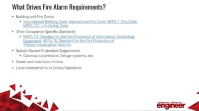
Fire alarm system design in commercial buildings is undergoing rapid transformation driven by evolving requirements in the latest editions of the International Building Code (IBC), International Fire Code (IFC) and NFPA 72: National Fire Alarm and Signaling Code. Modern buildings demand higher levels of system integration, improved pathway survivability, enhanced coordination with mechanical and architectural systems and allow for modern detection and communication technologies.
The 2024 editions of IBC and IFC establish when a fire alarm system is required, the level of protection appropriate for the occupancy type and when enhanced functions, such as emergency voice/alarm communication systems (EVACS), must be incorporated into the building’s life safety strategy. While NFPA 72-2025 governs system installation and performance, the IBC dictates the circumstances under which detection, notification and communication systems become mandatory.
Designers need to understand these “triggers” for accurate early-phase design decisions, particularly in mixed-use, multistory or assembly-intensive buildings where code pathways quickly diverge.
The IBC uses fire area as one of the primary decision points for determining when automatic detection and occupant notification are required. A fire area is defined as the aggregate floor area enclosed by fire barriers, fire walls, exterior walls, occupancy separations or horizontal assemblies. Smoke barriers or partitions are another physical element that can trigger requirements.
Differences between barriers, walls and partitions are specifically outlined in IBC and IFC and it’s vital for designers to not only understand the difference, but understand the requirements associated with each. A list of construction assemblies that have unique requirements are listed as follows:
- IBC 706 – Fire Walls
- IBC 707 – Fire Barriers
- IBC 708 – Fire Partitions
- IBC 709 – Smoke Barriers
- IBC 710 – Smoke Partitions
- IBC 711 – Floor and Roof Assemblies
- IBC 712 – Vertical Openings
- IBC 713 – Shaft Enclosures
Penetrations in any of these building assemblies require coordination with IBC 714 and a summary table is provided in Table 716.1 (1), (2) and (3). Additional requirements are outlined in IBC 717 for penetrations of the building assemblies listed above of ducts and air transfer openings. This section includes requirements for fire dampers, smoke dampers and combination fire/smoke dampers. The location of smoke dampers affects the activation methods that designers have at their disposal, as described in 717.3.3.2.
There are five methods listed in this section for smoke damper control and include detection in the duct, smoke detection in the associated corridor or smoke detection in the areas served. Designers need to identify the programming requirements associated with area smoke detection when that approach is used in lieu of duct smoke detection. Designers need to determine the effects of damper closure on the associated heating, ventilation and air conditioning (HVAC) system, to prevent restriction from increasing static pressure above recommended levels.
Smoke control systems
IBC Section 909 covers smoke control systems. In some buildings, shutting down the associated HVAC unit and all associated smoke dampers, makes sense upon detection of smoke in accordance with the programming sequence. In buildings where the HVAC unit is critical to the safety of building occupants, such as health care, the HVAC unit may want to remain in operation despite smoke damper closure.
For example, the designer may identify damper programming to keep the associated air handling unit(s) (AHU) running despite closure of a damper that affects less than 20% of the airflow for that AHU. This may be a popular option for health care buildings where the AHU serves operating rooms and nuisance airflow interruption would be problematic for the facility. This topic should be discussed with the building owner during design to set clear expectations for programming and operation.
IBC Section 907 identifies the fire alarm system requirements for each occupancy type. Common triggers include building area limits that vary based on the occupancy group type or number of occupants. For certain occupancies, fire area thresholds trigger automatic sprinkler requirements, which then cascade to additional alarm requirements such as waterflow monitoring, supervisory notifications and smoke detection systems.
Designers must verify fire/smoke area boundaries early, especially when architectural separations are not yet finalized. Misinterpretation of fire area limits can lead to under-specification of notification systems or incorrect assumptions regarding system type (e.g., horn/strobe versus EVACS). Smoke detection requirements for patient sleeping suites can be misinterpreted if the affected floor area is not understood. Unprotected connections such as communicating stairs or large floor openings can unify fire areas across floors unintentionally, shifting a building into higher alarm requirements.
Mixed-occupancy buildings require careful evaluation because the IBC applies the most restrictive requirements across shared egress and shared building systems. Separated occupancies and nonseparated occupancies, accessory occupancies and incidental use occupancies requiring enhanced protection may occur. For nonseparated mixed occupancies, the entire building must meet the most stringent fire alarm requirements of any individual occupancy group.
For example, introducing an A-2 (assembly) tenant into a primarily B-occupancy building can trigger notification requirements and EVACS thresholds for the entire structure. It’s also common to see I-2 occupancies (health care) combined with B occupancies (business) for medical offices and outpatient clinics.
Accessory uses, while exempt from full compliance as standalone occupancies, may require detection or alarm functions based on fire area or hazard characteristics. Incidental uses — such as furnace rooms, laundry processing or laboratories — may require dedicated detection or fire-barrier protection even when the main occupancy does not. These interactions make mixed-use structures a frequent source of design complications. Early classification and clear code-path documentation are critical to avoid changes late in design, when alarm system topology and notification load calculations are already established.
The IBC requires EVACS in several situations where evacuation needs or occupant load characteristics exceed basic horn/strobe notification capabilities. Common triggers include high-rise buildings, assembly occupancies with occupant loads greater than 1,000 or educational and institutional occupancies, depending on occupant load and mobility constraints
EVACS triggers are not tied to sprinkler protection level alone; they relate to evacuation complexity, communication clarity and multifloor coordination. Designers must also account for the fact that EVACS inherently triggers survivability requirements and then NFPA 72 identifies pathway survivability requirements often Level 2 — for distributed amplifier circuits, speaker pathways and risers. Failing to recognize an EVACS trigger early will significantly alter riser routing, amplifier capacity, battery sizing and acoustical considerations. When owners elect for EVACS due to risk assessments or campus standards, the resulting installation needs to comply with NFPA 72 as if it was required by IBC.
High-rise structures include several nested requirements that impact fire alarm system design. Fire command centers include alarm annunciators, controls and communication interfaces, as outlined in IBC Section 911. Almost all buildings require two-way fire department communication for firefighters, which takes the form of distributed antenna systems. Designers may encounter stairwell communication systems or enhanced survivability for fire alarm risers and pathways.
Assembly occupancies introduce additional considerations due to large occupant loads and open floor plans. Smoke layer development, evacuation modeling and acoustical conditions frequently justify EVACS deployment even when not explicitly triggered by occupant load. Designers must confirm visibility of visible notification appliances and ensure adequate sound pressure levels across large, reverberant spaces.
When smoke detection is required by the sections referenced above, designers have options for technologies beyond the traditional ionization and photoelectric detections. Multicriteria smoke detectors combine multiple sensing technologies — typically photoelectric, ionization, thermal and in some cases carbon monoxide or infrared particle analysis — to create a more stable detection profile.
NFPA 72 recognizes these devices as acceptable initiating devices, but their performance is context dependent. They are particularly effective in areas prone to nuisance alarms caused by dust, humidity or transient particulates, such as commercial kitchens (outside the cooking envelope), loading docks or high-air-movement office environments. Various manufacturers approach these products differently, which designers need to account for in open bid specifications.
The fundamental advantage of a multicriteria device lies in its ability to correlate sensor data. For example, a transient spike in particulate concentration will not trigger an alarm unless supported by thermal rise or additional optical obscuration. Conversely, smoldering fires can be identified earlier than with single-technology detectors, because the detection thresholds can adjust dynamically.
When designing around multicriteria detection, the engineer must confirm compatibility with the fire alarm control unit’s (FACU) logic processing and ensure that the device is listed for the intended environment. Placement rules follow Chapter 17 of NFPA 72, and designers should note that multicriteria listing requirements sometimes allow broader spacing than conventional spot detectors. These detectors increase project cost, so budget implications need to be addressed early in design.
Specialty detection and fire alarms
Air sampling detection (ASD) systems use a network of sampling tubes to actively draw air into a central sensing chamber. These systems are highly sensitive and suitable for environments where early detection is critical or where traditional spot detectors may not function reliably or not be readily accessible. Data centers, archival storage, clean rooms, cold storage facilities and high-value infrastructure are typical applications that can benefit from early detection. High ceilings or aesthetically pleasing ceilings can also benefit from ASD by remotely locating the detectors in accessible locations.
NFPA 72 acknowledges ASD systems under “air sampling-type detectors,” but installation specifics — including transport time, sampling point spacing and acceptable pipe lengths — are governed by manufacturer performance criteria and must be validated through engineered calculations. Designers must also ensure that sampling points remain accessible after installation, as these will be used for testing.
Beam detectors offer efficient coverage in large-volume spaces such as atria, theaters, convention centers and warehouses. Rather than using point detection at fixed spacing, beam detectors monitor optical obscuration along a long path length, allowing coverage of tens to hundreds of feet with relatively few devices. This reduces installation and wiring complexity in high or obstructed ceilings and facilitates testing.
NFPA 72, along with manufacturer’s guidelines, provides spacing and sensitivity guidance for beam detectors, but designers must account for accessibility and building elements or activities that could cause nuisance alarms or maintenance hassles. High-ceiling environments may experience delayed smoke layer descent, making beam detectors more reliable than spot detectors in the early stages of fire development.
However, excessive ambient dust or fog can cause false alarms unless multibeam or reflective beam technology is used. Beam detectors must maintain clear line-of-sight; interior design changes and rigging infrastructure should be reviewed during coordination to avoid obstructions.
Fire alarm notification requirements
Notification requirements can extend beyond the traditional horn or chime notification to voice/speech notification for EVACS. When EVACS is triggered or when a mass notification system is specified, the survivability level of the notification wiring needs to be determined.

NFPA 72 used to define multiple signaling line circuit (SLCs) pathway “styles,” each describing how a circuit must perform under fault conditions. This has been incorporated into pathway class designations and survivability levels, which provide additional detail. IFC sections 909.20.5.1, 913.2.2 and 1203.3 include requirements for survivability of critical circuits with reference to UL 2196. NFPA 72-2025 defines the various requirements for pathway class designations in 12.2, pathway survivability levels in 12.3 and shared pathway levels in 12.4.
For each project, the designer needs to determine the requirements for each need to be based on the project specific requirements and conditions. There is no clear table that allows designers to associate one project with one series of requirements. The pathway class designations are Class A, B, C, D, E, N or X. Each designation varies in requirements for path redundancy, fault tolerance, integrity monitoring and fault type indication.
Pathway separation, defined in NFPA 72 12.3, is required for Class A, N and X systems, with exceptions as noted. Pathway survivability levels include Level 0, 1, 2, 3 and 4. Each designation varies in cabling fire ratings, automatic sprinkler system requirements or a combination of. Designers can consider the requirements for cabling to remain operational in a fire, typically called circuit integrity (CI) cabling, though that designation is just one of several. NFPA 70-2025 Article 722 covers limited-energy cables for power-limited circuits, which supplements the existing NFPA 70 Article 760 Fire Alarm Systems.
CI cable and mineral insulated (MI) cable are the two most common cable types used for survivability. CI cable is tested to UL 2196 Fire Test for Circuit Integrity of Fire-Resistive Power, Instrumentation, Control and Data Cables and designed to maintain circuit operation for two hours under fire conditions. It supports typical installation techniques and bending radii like standard fire alarm cable, making it an attractive option for retrofits or systems with multiple bends and junction points.
However, CI cable still requires compatible hardware — CI-rated junction boxes, fasteners and support systems — to maintain listing compliance. MI cable provides a robust two-hour rating through its copper sheath and magnesium oxide insulation. It offers excellent mechanical and thermal durability, but installation demands more specialized training. Termination requires careful preparation, moisture control and compatible gland fittings.
While MI cable is common in industrial and mission critical facilities, its higher installation labor cost may limit its use in typical commercial buildings unless routing constraints or environmental exposure justify its advantages. NFPA 72 also allows survivability by routing standard fire alarm wiring through two-hour rated shafts or enclosures or listed fire-resistive cable assemblies.
Fire survivability
NFPA 72 now requires explicit documentation of pathway survivability on system drawings. Designers must identify survivability level, wiring method, fire-rated routing and any redundant pathway arrangements. Voltage-drop calculations must incorporate the chosen wiring type, especially for long CI or MI cable runs.
While these calculations are typically included with the submittal process, some projects may require the calculations to be submitted with design packages. Submittals should include manufacturer listings and installation instructions demonstrating how the method meets UL 2196 or equivalent fire-resistance testing. Clear documentation is crucial for coordination with architectural and structural disciplines — especially when fire-rated shafts, floor penetrations or enclosure space are needed to support more stringent pathways.
While health care facilities have long required robust pathway protection, commercial buildings such as high-rises, large assembly spaces and mixed-use buildings frequently require higher survivability pathways for EVACS and stairwell communication. These are not optional enhancements: IBC triggers for EVACS, combined with NFPA 72 survivability criteria, make pathway classification a code-driven design requirement. Design teams must treat fire alarm pathways with the same rigor applied to emergency power or generator distribution. The increasing reliance on networked fire alarm architecture makes survivability essential for maintaining communication integrity across nodes and distributed amplifiers.
Modern fire alarm systems increasingly rely on networked architectures, distributed processing and addressable signaling pathways to improve survivability and maintain system function during fault conditions. While legacy fire alarm systems often centralized control at a single FACU, current code cycles and manufacturer platforms favor multinode topologies, segmented SLCs and distributed amplifier networks to support complex evacuation strategies, high-rise communication requirements and integrated life safety functions. Addressable notification allows for evacuation zones to be adjusted without wiring changes and can reduce the burden of annual testing by automating the process.
Horn/strobe notification appliance circuit (NAC) design has traditionally relied on centralized NAC outputs originating at the main control panel or could be extended with cost-effective notification extender panels or NAC panels. Modern systems, however, increasingly incorporate distributed power supplies or networked audio amplifiers, particularly when EVACS is required or when long circuit lengths create voltage-drop challenges.
Distributed amplifiers reduce voltage drop across long NAC pathways, provide localized survivability options and prevent large-scale failures. This arrangement also improves evacuation messaging clarity by dedicating amplifiers to specific acoustic zones, when coordinated during design. NFPA 72 now expects amplifier locations, battery backup capacity and supervision pathways to be documented clearly. When EVACS is used, amplifier and speaker circuits often require Level 2 survivability, which influences riser routing and shaft availability.
Engineers must verify that distributed amplifiers remain operable under both primary and secondary power conditions and that loss of a single amplifier does not disable critical notification areas.
Large commercial buildings increasingly use networked FACU nodes rather than a single monolithic panel. Distributed nodes are placed on each floor (or alternate floors) to reduce the cost of CI wiring. Other components can be considered node, such as smoke control panels, elevator interfaces, graphical displays and fire command center systems. Nodes communicate using peer-to-peer protocols that allow any local node to initiate alarms, supervisory signals or control sequences. Fiber optic cabling is commonly used for communication speed.
A network-level failure should not suppress local alarm functions and NFPA 72 requires that essential operations occur even with loss of upstream or cross-link communication. For high-rise buildings, this enhances system robustness by eliminating single points of failure. Parallel networks, such as BACnet building automation system networks, should not be used as primary fire alarm communication pathways but may exchange monitored information through gateway interfaces. Fire alarm networks must remain electrically and functionally independent to meet performance and survivability criteria.
Segmenting SLC loops by floor, zone or hazard type improves both troubleshooting and survivability. For example, isolating smoke control-related devices onto separate SLC segments ensures that a general device fault cannot disable smoke control interfaces.
Similarly, elevator recall detectors must remain on reliable segments so that a single fault does not compromise life safety functions. NFPA 72 emphasizes that segmentation should prevent cascading failures and enable accurate annunciation. Proper device grouping also improves commissioning efficiency by allowing testing of individual fire zones without affecting unrelated building systems.
The evolution of fire alarm systems
Fire alarm systems are evolving toward more intelligent, self-diagnosing and interconnected architectures. While existing codes — primarily NFPA 72 and the IBC — do not yet mandate many of these capabilities, manufacturers and some building operators are already adopting technologies that extend system visibility, reduce maintenance burden and improve occupant communication during emergency conditions. As smart building strategies mature across lighting, access control and HVAC, the fire alarm system is becoming an increasingly integrated component of a unified operational platform. Several emerging trends point toward how fire alarm systems will function over the next decade.
Modern addressable fire alarm systems gather significant device-level data: sensitivity drift, contamination levels, response profiles and communication stability. Historically, this data has been used for periodic maintenance and troubleshooting, but next-generation systems are applying machine-learning analytics to detect patterns not apparent during traditional testing. These platforms should not alter the code-required testing intervals, but they can provide additional documentation and trend data that support compliance and improve operational reliability. Predictive analytics may eventually support performance-based maintenance strategies, especially in mission critical environments where unplanned outages carry significant cost.
EVACS are transitioning from analog amplifier chains to fully digital audio distribution using networked amplifiers, redundant pathways and packet-based routing. Unlike legacy systems — where audio was distributed over dedicated conductors — digital EVACS platforms encode audio into data streams and route it through fault-tolerant network infrastructure.
As these systems expand, designers will need to evaluate network survivability, amplifier redundancy and compatibility with NFPA 72 requirements for priority routing and message control. Digital architectures also expand opportunities for integration with mass-notification and public-address systems.
The design of modern fire alarm systems includes more than simply placing detection and notification appliances. Designers need to align the project budget with both code and project requirements, taking the contents of this article into account as well. Reading the applicable code for every project is an important step, not only because running off memory alone is dangerous, but each code evolves and there is always more to learn.
Each project requires a conversation with the project architect to discuss how they are handling barriers, areas, suites, separations, etc. Not only will this have implications on fire/smoke dampers but may influence the specification of nodes and evacuation signaling zones (where applicable). When designers are determining the building risk assessments, the cabling survivability definitions are another layer of detail that the drawings and specifications need to define. The architecture of the fire alarm system, in conjunction with the building type and occupant risk, will drive the system complexity and resiliency.