To ensure safe electrical design, the NEC includes several sections covering requirements for the installation of low-voltage electric motors.
Learning objectives
- Understand key NFPA 70: National Electrical Code (NEC) requirements for motor installations during project design.
- Know what information to look for on a motor nameplate.
- Learn how to select the appropriate conductors, motor branch-circuit protection and disconnecting means for a new motor installation.
Motor insights
- Electric motors convert electrical energy into mechanical energy and require careful consideration of size, type and safety standards for proper operation.
- NEC Article 430 outlines detailed requirements for motor circuits, including conductor sizing, short-circuit protection, motor controllers and disconnecting means to ensure safe and efficient motor performance.
Electric motors are a commonly used machine that converts electrical energy into mechanical energy. They come in a variety of sizes and types and are used for numerous operations. When a motor is required for an industrial process, there are important considerations to make to ensure safe and functional operation.
NFPA 70: National Electrical Code (NEC) Article 430 provides requirements for electric motors and necessary electric circuitry. Some key parts pertinent during project design are:
- Part I, general: Provides definitions and general requirements, including motor marking, code letters, spacing, location and amperage ratings.
- Part II, motor circuit conductors: Covers motor circuit conductors, which provide power to motors via copper or aluminum wires.
- Part IV, motor branch-circuit short-circuit and ground-fault protection: Covers circuiting and protection for motor branch-circuit conductors and motors against short-circuit and ground-fault overcurrent.
- Part VII, motor controllers: Covers motor starting and stopping, including reduced-voltage starting and speed control.
- Part IX, disconnecting means: Covers means of disconnecting motors and controllers from electrical circuits, which are typically located near the motor.
Part I: General
As an introduction to Article 430, this part provides an overview of all other parts of Article 430. It includes an informational one-line to help visualize where critical components of a motor circuit are located, starting at the power supply and ending at the motor. This part provides information regarding minimum conductor ampacities for given motor types and sizes, motor marking and terminal requirements and acceptable motor locations.
Some of the most referenced parts of Article 430 are the full-load current (FLC) motor amperage tables, which are in Part XIV of Article 430, and discussed in Part I. Depending on whether a motor is direct current (dc) or single-, two- or three-phase alternating current (ac) induction, synchronous or polyphase type, the NEC tables with minimum amperage ratings must be used. These are NEC tables 430.247, 430.248, 430.249, 430.250, 430.251(A) and 430.251(B). The tables list maximum horsepower and voltage values based on motor type; the largest listed is 2,300 volts (V) and 500 horsepower (hp).
Motors within the listed tables must use the included amperage values as the minimum basis for selecting electrical equipment, even if the motor nameplate full-load amperage (FLA) is less than the NEC table FLC. However, motor nameplates with greater FLAs must use the greater nameplate FLA value.
While FLA and FLC are related, FLA is the actual motor current as shown on the motor nameplate and FLC is a standard value found in the NEC. For example, NEC table 430.250 states the FLC for a 460 V, 15 hp, induction-type motor is 21, but the motor nameplate could have a FLA of 23, requiring the electrical equipment sizes to be based on the motor FLA of 23 instead of the NEC FLC of 21. This is common for motors built for low speeds, especially 1,200 revolutions per minute or less.
In addition to the motor FLA, there are multiple other markings that motors must have to comply with Article 430. The markings provide personnel with key operational data to ensure the motor is used correctly and safely and is functioning properly. The key marking requirements are as follows: manufacturer’s name, rated voltage, FLA, rated frequency, rated full-load speed, rated temperature rise, time rating, secondary voltage, field current and voltage for dc-excited synchronous motors, winding and the locked rotor code letter (see Figure 1).
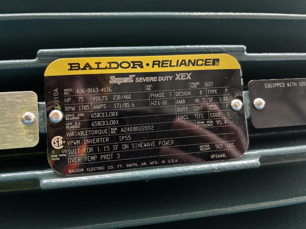
The locked rotor code letter is important because it corresponds to a kilovolt-amperes per horsepower rating for a locked rotor. It helps inform personnel about the starting current that the motor will draw. As previously discussed, the motor FLA is important to ensure electrical equipment is sized appropriately. Other items listed are just as important to ensure the motor is properly rated for its application, environment and associated electrical equipment.
For the motor terminals, it is important they are marked to indicate proper connections and shall be connected with copper conductors unless identified for use with a different conductor. Additional guidance is provided for torque requirements, wire spacing within an enclosure and wire-bending space in an enclosure.
To ensure wires entering the motor terminals can be properly connected, NEC 430.10(B) provides minimum wire-bending space at the terminals of enclosed motor controllers. It provides the minimum space required to bend wires within an enclosure for given conductor sizes. This is a vital consideration when selecting a motor and the power conductors for the motor. Often manufacturers will have conductor size limits, which should be determined before procuring the power conductors.
The location of the motor must also be considered. The motor must be placed in a location that allows for adequate ventilation and proper maintenance such as lubricating bearings and replacing bushings or motor windings.
Part II: Motor circuit conductors
Part II of Section 430 focuses on motor circuit conductor requirements. Motor circuit conductors carry the motor current. Part II specifies the ampacities motor circuit conductors can carry without overheating and provides the necessary steps and information to properly size and protect the feeder connections for a single motor, motors in multiple-motor systems or multiple motors fed from a single feeder.
If only a single continuous-duty motor is being supplied, conductors shall be 125% of the motor FLC obtained from the Part II ampacity tables or the motor nameplate FLA for motors with a nameplate value larger than the NEC FLC value. For multiple motor and nonmotor loads, the motor circuit conductors must be sized to handle the sum of:
- 125% of the full-load current rating of the largest motor load.
- 100% of the full-load current rating of all other motors in the group.
- 100% of the noncontinuous nonmotor load.
- 125% of the continuous nonmotor load.
The NEC defines a continuous load to be a load operating at maximum current for three or more hours. For example, lights are continuous loads and general-purpose receptacles are noncontinuous loads.
If the largest motor includes multiple motors of the same size, only one of the largest motors must be included at 125% FLC and the others can be included at 100% FLC. Article 430.24 provides for a few exceptions, such as exception No. 3, which allows for the removal of any motors or other loads from the total summation when the circuitry is interlocked to prevent simultaneous operation with the other motors and nonmotor loads. The example exception could reduce costs by removing standby loads from the total load sizing requirements.
Part IV: Motor branch-circuit short-circuit and ground-fault protection
Part IV of Article 430 focuses on short-circuit and ground-fault protection devices for motor‑branch circuit conductors, with emphasis on the appropriate sizing of short-circuit and ground-fault devices to clear faults quickly while still allowing normal motor starting applications. Every motor branch-circuit short-circuit and ground-fault protective device must comply with Section 430.52(B), which states the protective device must be capable of carrying the starting current of the motor.
Table 430.52 (C)(1) has the maximum rating or setting for motor branch-circuit short-circuit and ground-fault protective devices. This table has multiple values depending on the type of motor and type of protection device. Motor types include single phase, ac polyphase, squirrel cage, Design B energy-efficient/premium efficiency, synchronous, wound rotor and dc. Protective device types include nontime-delay fuses, dual element (time-delay) fuses, instantaneous trip breakers and inverse time breakers.
As noted in Part II, the ampacity of the feeder conductors must be at least 125% of the FLC of the largest motor; however, they could be rated for a higher ampacity if they are protected by the motor branch-circuit protection device. The maximum values can be much higher than 125% of the motor FLC.
Dual-element (time-delay) fuses have a standard maximum rating of 175% of the motor’s FLC. Inverse time breakers can be rated up to 250% of the motor’s FLC. Non-time-delay fuses can be rated up to 300% of the motor’s FLC. Instantaneous trip breakers are typically allowed to be rated as high as 800% of the motor’s FLC, however can go up to 1,100% for Design B energy-efficient or premium efficiency motors.
Subsections within 430.52 provide exceptions allowing for different percentages based on various factors. Additionally, the unique requirements for several motors/other loads, other group installations and motor taps outlined in 430.53 are based on several motors or loads on one branch circuit.
Part VII: Motor controllers
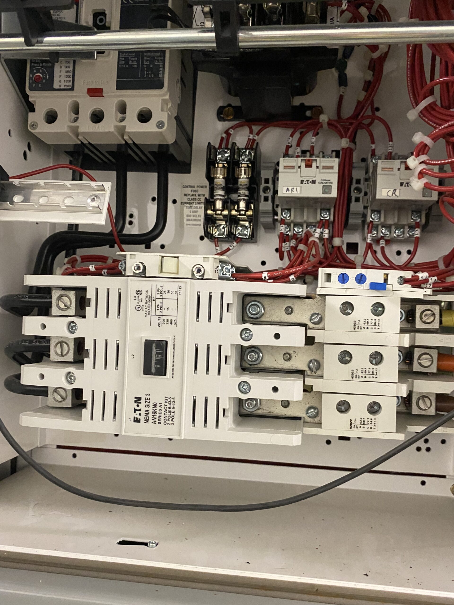
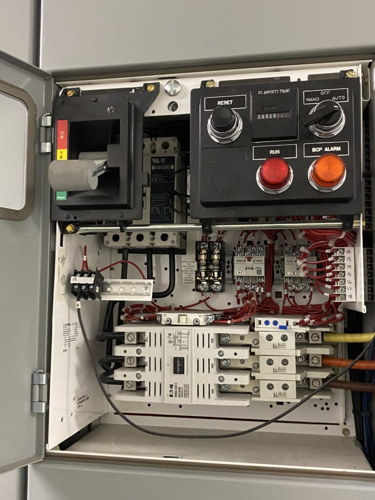
Motor controllers are the focus of Part VII. Motor controllers are responsible for starting, stopping, regulating and protecting motors during operation. The conductors, feeders and protective devices discussed in earlier paragraphs are critical to safety and efficiency. Controllers are positioned between the electrical supply and the motor, which makes them an important part of the installation. Motor controllers can include a manual switch, magnetic starter, variable frequency drive (VFD) or — depending on the complexity of the design — any combination of these parts. Figure 2 shows a motor branch-circuit protective device and a motor controller within a motor control center (MCC) compartment.
Articles 430.81 to 430.90 outline the minimum code requirements for motor controllers. For stationary motors rated at 1/8 hp or less that are designed to operate continuously without risk of damage from overloads or starting failures (like clock motors), the branch-circuit disconnect can also function as the motor controller. In contrast, portable motors of 1/3 hp or less can have a motor controller that is an attachment plug and a receptacle or cord connector.
According to 430.82, each motor controller must be able to start and stop the motor that it will be controlling and be able to interrupt the locked rotor current. The motor controller’s horsepower rating must be equal to or greater than the motor’s horsepower, which will ensure the controller will start and stop the motor under load. An inverse time circuit breaker that is rated in amperes (A) rather than horsepower can be used as a motor controller for all motors; however, if it is also used for overload protection, it must comply with the proper overload protection guidelines.
Similarly, molded-case switches rated in amperes are eligible to act as a motor controller for all motors. The molded-case switch must be properly rated for the motor’s FLC. If a controller does not function as a disconnection device, it only needs to open the number of conductors necessary to stop the motor. For a dc or single-phase motor circuit, one conductor is sufficient. For a three-phase motor circuit, two conductors must be opened. For a two-phase motor circuit, three conductors are required.
Each motor shall have its own motor controller, ensuring that motors can be independently started or stopped without affecting other connected equipment. This setup is critical for safe maintenance, troubleshooting and system flexibility. With a larger system, this application will help avoid unnecessary downtime to multiple systems if only one motor requires attention.
Part IX: Disconnecting means
An essential safety measure for any motor installation is the ability to disconnect power for various reasons including maintenance, servicing or emergencies. Part IX of Article 430 outlines the requirements for disconnection methods. Disconnecting means are devices capable of safely and reliably isolating motors and motor controllers from all sources of power.
In accordance with 430.102, a disconnecting means must be installed for each motor and motor controller. The disconnect must be within sight of the motor location and the motor controller location and it must not be more than 50 feet away from the location. Following these guidelines allows personnel to safely maintain equipment within sight of the disconnecting means, to reduce the chance of someone turning the equipment on while it is being serviced.
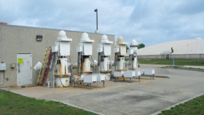
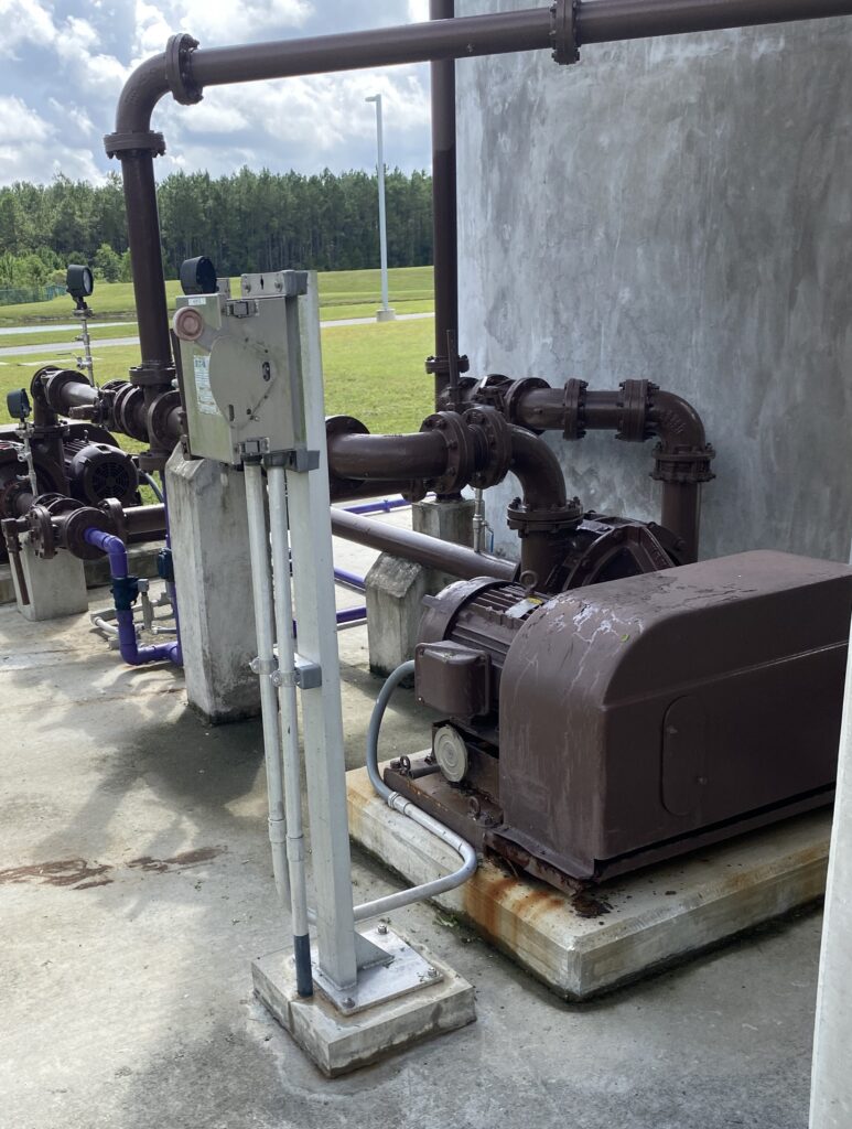
If it is not possible to have the disconnecting means in sight of both the motor and the motor controller, a separate disconnecting means must be provided at the motor location. Figure 3 shows a disconnect switch installed near a motor. The disconnecting means must be capable of opening all ungrounded conductors and must indicate whether it is in the open or closed position. In three-phase systems, all three phases must be able to be disconnected. For single-phase motors, this typically means two conductors.
The motor disconnecting means is not required if it introduces additional or increased hazards or if its installation is impractical It is also not required for industrial installations with written safety procedures in place, where it is ensured that only qualified personnels will service the equipment.
There are areas where these exceptions are helpful, such as in hazardous areas that require expensive explosion proof enclosures or large outdoor rated motors that would require large disconnecting means with expensive material, such as stainless steel.. A good rule of thumb for the size of an outdoor motor disconnect switch is 200 A or smaller. For motors that would require a disconnect switch larger than 200 A, where only qualified personnel will service the equipment, an emergency stop button can be installed nearby for personnel safety instead.
While a disconnect switch is a common type of disconnecting means, there are several acceptable types. Section 430.109(A) states that the disconnecting means must be a switch, circuit breaker or motor controller, provided it is readily accessible and free of obstructions.
The disconnecting means for motor circuits rated at 100 V nominal or less must have a current rating of no less than 115% of the motor’s FLC. This ensures that the disconnect completely isolates the motor from all power sources. For combination loads, which involve two or more motors connected through a single disconnecting means, the current rating must account for the total sum of all currents. This includes both resistive loads and conditions at locked rotor status.