When specifying a VFD to control a motor load, consider factors for both the motor and the VFD to ensure compatibility and proper operation.
Learning objectives
- Understand variable frequency drive (VFD) design considerations.
- Review NFPA 70: National Electrical Code (NEC) requirements for motor and VFD installations.
- Know the motor design considerations when specifying a VFD.
Motor insights
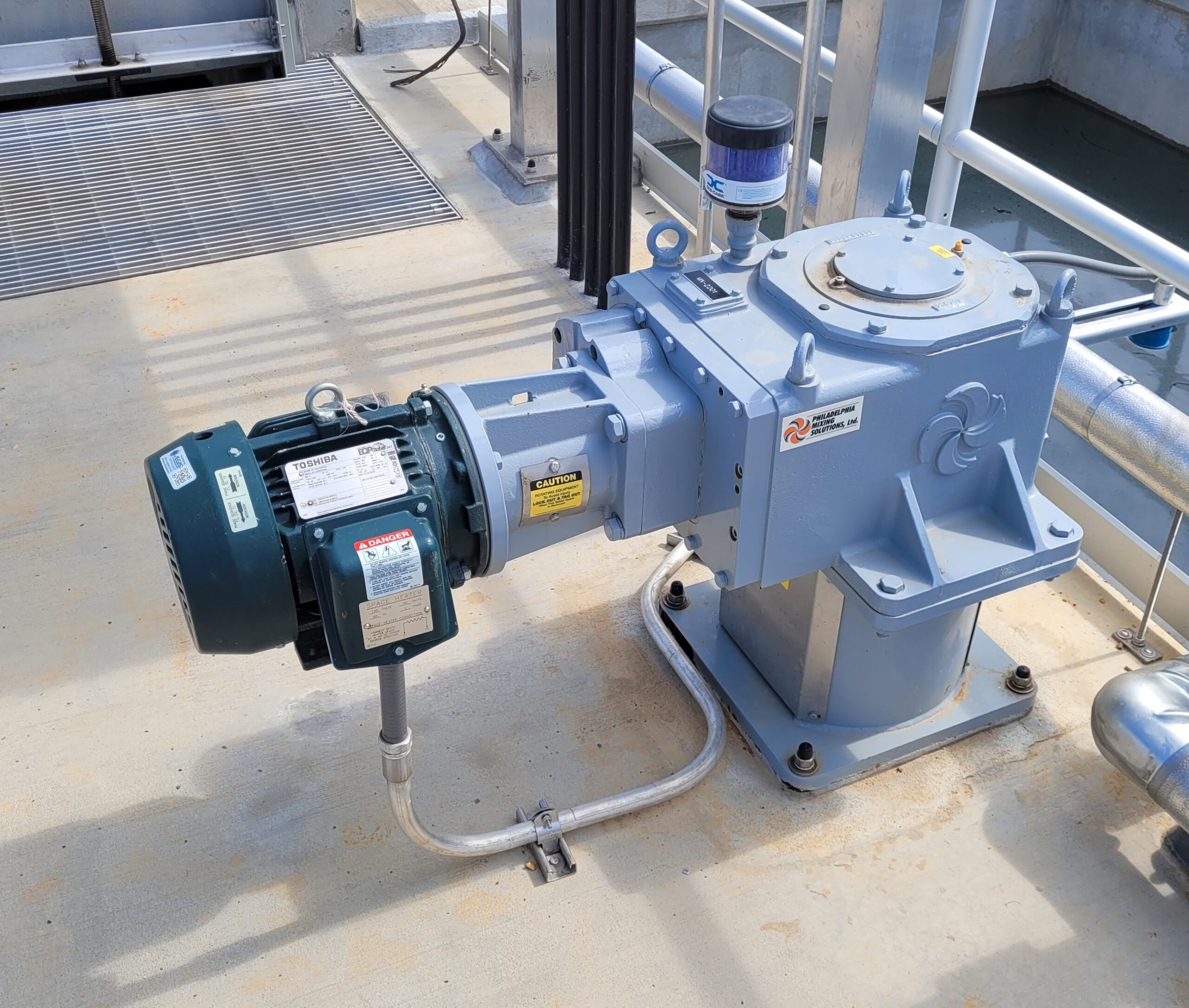
- When specifying a variable frequency drive, it must be compatible with the motor and the driven load, as drives are selected based on load type and motor ampacity rather than horsepower.
- Because drives can generate harmonics that overheat motor windings and cables, harmonic mitigation components and inverter duty-rated motors are essential to protect the motor and maintain system efficiency.
One of the main considerations to account for when specifying a variable frequency drive (VFD) is that it needs to be compatible with the motor and driven load. VFDs are rated for standard duty or heavy duty and are selected based on the load type.
Load type may vary, as a single VFD can control multiple motors. Standard-duty VFDs are typically used for variable torque loads, such as centrifugal pumps or fans. Heavy-duty VFDs are typically used for constant torque loads, such as conveyors, extruders or other constant heavy loads.
VFDs are also rated by their ampacity, not horsepower (hp), so it is important to inform the VFD manufacturer of the ampacity of a motor so they can properly match the VFD to the motor, especially when motors have higher than typical full-load ampacities (e.g., low speed, submersible or high torque motors).
Harmonic mitigation for VFDs
A VFD is commonly used for motors in various applications to control the speed of the respective motor as compared to an across-the-line starter or a reduced-voltage soft starter that cannot control the speed. The VFD for the application optimizes the respective process and reduces energy consumption.
All VFDs contain three common stages: input rectifier, direct current bus and output inverter.
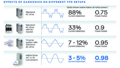
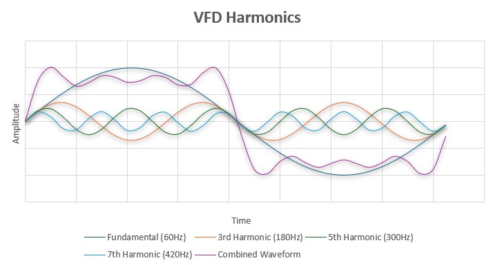
VFDs are considered nonlinear loads and thus introduce harmonics into the electrical system. For linear loads, the voltage and current waveforms are sinusoidal while in sync with one another. Nonlinear loads create nonsinusoidal waveforms with abrupt pulses on the waveforms, thus causing distortion of the waveforms.
Examples of nonlinear loads include fluorescent lighting with electronic ballasts, computers and power electronics including VFDs. The distorted waveforms generate harmonics into the electrical system through the line side and the load side of the device. Harmonics on the line side will affect upstream devices through breakers nuisance tripping (thus requiring oversized generators) and potentially back-feeding into the utility.
Also, there is an impact to overall service power factor for facilities with large quantities of VFDs, such as manufacturing plants.
On the load side, harmonics can cause overheating within the motor windings and respective cables to the motor. These harmonics are not desired within an electrical system because they create current and voltage distortion on the fundamental alternating current waveform by frequencies that are multiples of the fundamental (e.g., 3rd, 5th, 7th). The combined waveform is found by adding the multiples with the fundamental waveform that is causing distortion on the combined waveform, which starts creating a nonsinusoidal waveform.
Harmonic mitigation techniques are used to reduce these unwanted distortions and are achieved with additional components on the input and output sides of the VFD or within the input rectifier of the VFD. It is considered a best practice to design an electrical system to meet the harmonic guidelines set forth in IEEE 519: Standard for Harmonic Control in Electric Power Systems.
Harmonic mitigation techniques: Input side of VFDs
The following are typical methods and technologies used to help mitigate harmonics caused by VFDs.
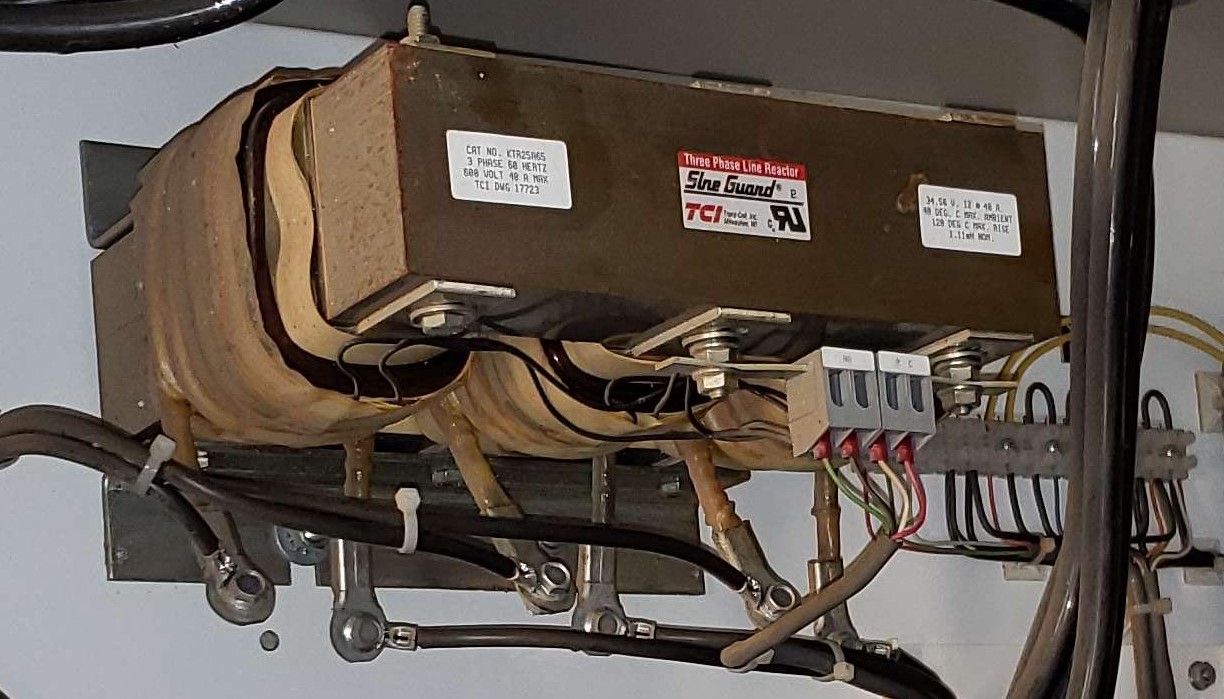
Line reactors: The simplest and most cost-effective type of harmonic mitigation is typically a line reactor, which is an iron or steel core with copper-wound coils around the core(s). There are two common types of line reactors: 3% and 5% impedance. A higher percentage will reduce more harmonics, but typically anything past 5% is not common due to voltage drop issues.
These are generally used with low-voltage, small hp motor loads or are combined with other types of harmonic mitigation, as they generally do not provide enough harmonic mitigation for large hp motor loads.
Passive harmonic filter: The passive harmonic filters consist of a reactor and capacitor configured in either series or parallel, depending on the exact type being used. A passive filter with the reactor and capacitor in parallel will be tuned to a specific frequency of the fundamental, typically either to the 5th or 7th to filter out those harmonics. These are more costly than line reactors but can achieve greater harmonic reduction.
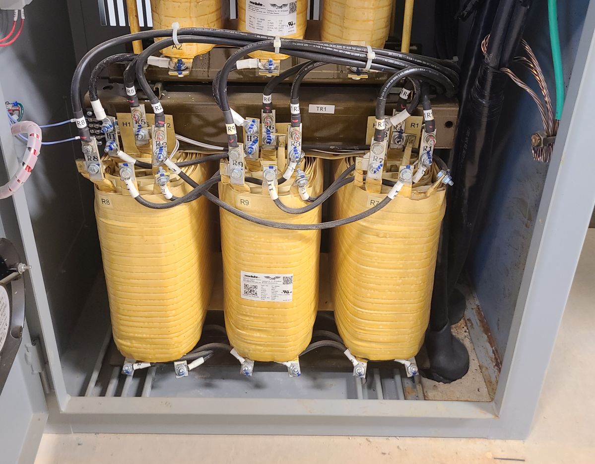
Multipulse: Multipulse VFDs come in a variety of different configurations; 6-, 12- and 18‑pulse are the most common for low-voltage applications. The number of pulses refers to the quantity of the diodes in the input rectifier stage of the VFD. These are created by providing a phase-shifting transformer before the rectifier section of the VFD. The transformer then has multiple secondary windings, each phase shifted from each other and each connected to a 6-pulse diode bridge, thus creating a pulse quantity higher than six.
The greater the pulse count within the input rectifier, the greater the harmonic mitigation and, thus, the closer to a true sinewave output. However, higher-pulse VFDs are more costly and are not as commonly specified with newer mitigation techniques being developed.
Active front-end: In an active front-end VFD, the diodes within the input rectifier stage are replaced with insulated gate bipolar transistors (IGBTs). This allows for controlled switching on both the rectifier and inverter sections of the VFD. The IGBTs have higher frequency switching capabilities and create significantly less harmonic distortion than previous technologies mentioned. This type of VFD is typically used for larger hp motor loads generally greater than 100 hp or for facilities that require increased harmonic mitigation.
Active filter: Active filters can actively sense harmonics and inject equal and opposite currents to cancel harmonics. These are commonly integrated within motor control centers or as stand-alone units connected to the bus of a distribution board where they can mitigate the harmonics or multiple VFDs at once.
This option is good when many VFDs (with minimal harmonic mitigation technology) are fed from a common distribution board. The potential downside of this option is that it does not allow for redundancy unless multiple units are installed.
Harmonic mitigation techniques: Load side of VFDs
Output filters are included after the output inverter section of the VFD. These filters are used to help smooth the VFDs output from the pulse-width modulated (PWM) signal and protect the motor against transient voltage spikes. There are three common types of output filters:
- Load reactor: Like a line reactor, a load reactor is constructed identically to a line reactor. The only difference is that the load reactor is located on the “load” side of the VFD instead of the “line” side. This is the most cost-effective option for installations where the motor is located up to 100 feet from the respective VFD, depending on the manufacturer, amperage rating, VFD type and if the motor is inverter-duty rated.
- dV/dT filter: A dV/dt filter slows down the rate of voltage increase to reduce the magnitude of the voltage spikes. In applications where the motor is located 500 to 1,000 feet away, a dV/dt filter may be more appropriate as these filters are better suited for longer cable lengths.
- Sinewave filter: A sinewave filter is the most expensive option but will provide the best protection for the motor against voltage spikes. Another benefit of the sinewave filter is that it can be used for installations up to 15,000 feet. However, other factors such as cable sizing due to voltage drop must be considered when there is significant distance between the VFD and motor.
Output circuitry of VFD cables
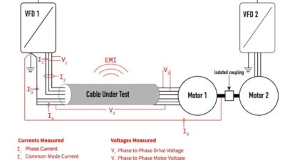
A VFD cable is a specialized constructed cable that helps reduce electromagnetic interference (EMI) and transient voltage spikes. VFD cables are constructed with an outer insulation jacket, inner shielding and symmetrically configured insulated phase conductors and ground conductors.
VFDs create a substantial amount of electrical noise owing to the high-frequency transistor switching; therefore, the additional shielding in VFD cables around the conductors will help mitigate EMI from affecting nearby signal wiring. Also, the low capacitance design of VFD cables helps to reduce the magnitude of the voltage spikes delivered to the motor.
To protect the VFD cables against voltage spikes, these are typically specified with voltage ratings of 1,000 volts (V), 2,000 V and higher. However, it is critical to properly terminate and bond the phase conductors, ground conductors and shield within the jacketed cable to obtain benefits from the VFD cable.
If specialized VFD cable is not used for value engineering reasons, it is recommended to use XHHW wire instead of THHN wire because it has more robust insulation that can withstand higher voltage spikes. Also, it is recommended to use steel conduit instead of aluminum to help reduce EMI.
Specifying an inverter duty-rated motor
Motors want a traditional 60-hertz sinewave. VFDs send a PWM waveform to the motor that is electrically noisy when compared to that of a traditional sinewave. Also, due to the high frequency switching of transistors in the inverter section of the VFD and the inherent stray inductance in the circuit, voltage spikes are induced and added to the main voltage delivered to the motor. This can lead to voltages as high as two to three times the rated voltage.
VFDs also can operate the motor at a much lower speed than the rated speed of the motor, which can lead to cooling problems for fan-cooled motors, as the fan will also operate at a lower speed. These items can cause extra stress on the motor winding insulation, breaking it down and leading to winding short circuits and motor failure.
Because of these factors, it is important to specify motors as inverter duty-rated when driven by VFDs. A motor with the inverter duty rating (as opposed to a general-purpose motor) comes with the following enhancements, per NEMA MG1-2024, Part 31:
- Winding temperature rise limitations at any point along the operating curve. For example, Class F insulation allows a maximum intermittent winding temperature rise of 140°C above a 40°C ambient (when measured by embedded detector). This provides thermal management to handle variable speeds and loads as general-purpose motors can overheat when operated lower than the rated speed.
- Higher level of insulation to withstand voltage spikes at a minimum of 3.1 times the rated voltage of the motor (for motors rated less than or equal to 600 V).
- Torque guarantees at defined frequencies.
- Optimized for sound and vibration reduction; however, it is impossible to address all sound and vibration concerns with motor design alone.
- Ability to operate with:
- Voltage fluctuation of ±10% of rated voltage
- Two minutes of overspeed condition without damage
- Excess current for no less than 1 minute of 110%, with at least nine minutes between overloads, 125% with at least 28 minutes between overloads and 150% with at least 60 minutes between overloads.
Motor service factor
A motor’s service factor is the percentage of power that a motor can handle above its nameplate rating when operating at rated voltage without overheating or damaging the motor. This allows a motor to account for overload conditions. A typical motor service factor is 1.15; however, fractional hp or specialized motors can reach 1.5.
Operating at any service factor greater than 1.0 can cause the motor speed, efficiency and power factor to be different than at rated load. Also, operating continuously at a service factor greater than 1.0 will reduce the motor’s lifespan. Therefore, to ensure longevity of a motor, it is important to select one that can continuously operate the load without intentionally going into the service factor window.
While a motor will have a service factor above 1.0 when running at constant speed, the service factor of that same motor will be 1.0 when operating on VFD power. This is because a VFD causes extra heating in the motor and the service factor can generally account for overloading or excess heat due to VFD operation, but not both. Therefore, a motor operating on VFD will no longer have service factor protection if it were to operate above its nameplate rating.
Motor-bearing protection
Motors using a VFD are susceptible to bearing damage due to the production of stray voltages produced by the VFD. The stray voltages are typically caused by one of the following:
- Capacitance coupling of the common mode VFD voltage on the motor shaft.
- High-frequency currents within the VFD’s output circulating through the motor frame, which induces voltage on the motor shaft.
Both types of voltages can potentially build up until they are large enough to discharge current through one or both bearings. Over time, this will cause damage to the motor bearings and degrade the bearing grease, thus causing increased friction and noise. If this discharging through the bearings continues to happen, it will most likely end in complete failure of the bearings.
To address this issue, a few different techniques can be applied to the motor: providing shaft grounding rings, insulating bearings, providing filters to the VFD or improving the grounding system. Two common methods are:
- Shaft grounding rings
- Insulating motor bearings.
Shaft grounding rings installed on the motor shaft, usually on the drive end, can help properly dissipate these stray voltages to reduce the risk of damage and premature failure of motor bearings. Additionally, a grounding strap for the motor enclosure is used with a shaft grounding ring to provide a low-impedance path to the electrical grounding system, as required by NFPA 70: National Electrical Code (NEC).
The other option is to insulate one or both bearings. Insulating the bearings will prevent current from passing through them, but it does not eliminate the voltage and current issue. These currents may travel through other parts of the motor or through attached equipment. However, insulating bearings is a viable option when shaft grounding rings are not applicable, such as in classified spaces.
The best practice is to provide a shaft grounding ring for all motors driven by VFDs, where possible. For motors that exceed 100 hp, the ring should be paired with insulating the nondrive end bearing.
Motor winding overtemperature protection
Consider overtemperature protection for motors to avoid premature failure of the motor. These protections are necessary to protect the motor windings from overtemperature events.
Motors are susceptible to overtemperature due to several potential issues, including:
- Overloads are when the motor is running past its design capacity and attempting to draw in more current than the motor windings are designed to handle.
- Improper ventilation can occur when the space in which the motor is located has not been adequately cooled with proper airflow. Another possibility could be debris blockage within the air intake and outtake vents causing a buildup of heat produced within the motor enclosure.
- Voltage issues can occur when the voltage applied to the motor is too low, potentially due to voltage drop or unbalanced power supply and the motor attempts to draw more current, thereby causing excessive heating.
To protect the motor from these overtemperature conditions, the NEC-2023 Article 430.126 requires one of the following four protection measures be implemented when the motor uses a VFD. These protection measures are for motors larger than 1 hp:
- Motor thermal protector in accordance with NEC Article 430.32. There are four options for providing a thermal protector:
- Separate overload device responsive to motor currents
- Thermal protector integral with the motor or an electronically protected motor
- Protective device integral with the motor
- Protective device having embedded temperature detectors for motors larger than 1,500 hp
- VFDs capable of load- and speed-sensitive overload protection and thermal memory retention upon shutdown or power loss.
- Overtemperature protection relay using thermal sensors embedded in the motor and meeting the requirements of option 2 (above).
- Thermal sensor embedded in the motor whose communications are received and acted upon by the VFD.
Motor thermal protectors encompass three common types of overtemperature protection:
- Temperature switches: A thermostat switch is an embedded bimetallic temperature switch within the windings of the motor. This is either a normally closed or normally open switch that will change position based on the set temperature. This is the cheapest option and is commonly used on motors of 250 hp or less.
- Thermistors: Thermistors are thermal detectors embedded into the motor windings that vary sharply in resistance when it reaches the temperature setpoint. These require a controller module to adjust the setpoint.
- Resistance temperature detectors (RTDs): RTDs are considered the best devices for thermal protection because these will give an exact temperature. A warning setpoint alarm can be adjusted before the temperature gets too high. Like thermistors, this will also require a control module to adjust settings. RTDs are typically used in larger hp motors; consider these for applications that start around 400 hp.