The 2019 edition of NFPA 110: Standard for Emergency and Standby Power Systems includes a variety of revisions and updates that clarify design
Learning Objectives
- Understand the changes to the 2019 edition of NFPA 110: Standard for Emergency and Standby Power Systems.
- Learn the definitions of EPS and EPSS.
- Consider classifications of type, class and level.
The 2019 edition of NFPA 110: Standard for Emergency and Standby Power Systems includes a variety of revisions and updates that clarify the intent of the technical committee with a few added requirements. Code references in this article are to the 2019 edition, unless stated otherwise. One of the changes is a revision to the description of the primary source, renamed to “normal” to align with other sections and NFPA 70: National Electrical Code. NEC does not define when a standby power system is needed, but explains how to implement, test and maintain the functionality of these systems.
NFPA 110 has two primary equipment and system definitions that will be referenced throughout this article: emergency power supply and emergency power supply system. The EPS is the source of energy that provides an alternate source when the primary or normal, source fails and includes any common bussing or overcurrent protection devices associated with the alternate source. The EPSS is the equipment that distributes the electrical energy generated by the EPS.
The scope of EPSS equipment includes every distribution component from the output of the EPS to the transfer switch(es). See Figure 1 for a delineation of EPS and EPSS scope.
Defining parameters
Before the specific requirements of NFPA 110 can be applied, there are three parameters defined in Chapter 4 that need to be determined: type, class and level. The type refers to the amount of time, in seconds, that is allowed to occur between the loss of the primary or normal, source and the acceptance of the alternate or standby, source. Options for power restoration time are 10 seconds, 60 seconds, 120 seconds, manual and uninterruptible. Uninterruptible is a classification used for uninterruptable power supply systems and is not applied to standby generator systems.
The “class” refers to the amount of runtime, in hours, that is required before the alternate or standby, source requires refueling or recharging. Options for run time include five minutes, 15 minutes, two hours, six hours, 48 hours and class X. Class X is a timeframe that is required by other sections of NFPA 110, other codes or the authority having jurisdiction.
Level classification relates to the type of loads served and is specified by other codes. A level 1 system has more stringent requirements than a level 2 system. Systems can be classified as level 1 or level 2 with the difference being the risk to loss of human life given the failure of the system. If building occupants are at risk of serious injury or death due to a failure of the system to function, then the system must be classified as level 1, as noted in NFPA 110 4.4.1.
Examples of this include, but are not limited to, health care as required by NFPA 99: Health Care Facilities Code and high-rise occupancy types as required by the International Building Code. Level 2 systems are specified when loss of life is not a possibility, given a failure of the EPS or EPSS.
One example of a level 2 load could be air handling unit or building conditioning equipment. Unless expressly required in other building codes, a risk analysis should be performed to determine which level is applicable to the system.
Designers familiar with NFPA 99 may notice that the level classification for an EPS and EPSS is similar, but different, from the category classification of patient care spaces in NFPA 99 Chapter 4. For example, 2018 NFPA 99 identifies a type 1 essential electrical system and a type 2 EES; those definitions correlate to a level 1 EPSS or a level 2 EPSS, respectively. Engineers should pay careful attention to how terminology is used in each code section referenced.
NFPA 110 does not define which of these three classifications are applicable to which types of systems, rather those are defined in other building or NFPA codes. Examples of other code sections that reference NFPA 110 and identify the classifications are:
- The 2018 edition of NFPA 101 7.2.3.12 requires a type 60, class 2, level 2 EPSS for pressurization systems serving building egress enclosures.
- The 2018 edition of NFPA 99 6.7.1.2.4.1 requires type 10, class X, level 1 generator sets and references NFPA 110 for health care occupancies.
- The 2018 edition of NFPA 101 11.8.5.3.1 requires a type 60, class 1, level 1 standby power system be provided for high-rise structures.
Section A.4.2 of the annex in NFPA 110 identifies that class X usually consists of 48- or 96-hour run times and correlates a 96-hour run time with level 1 systems in category C or higher seismic design categories. The idea behind fuel storage that lasts several days is due to the proclivity of natural disasters that could prevent fuel delivery to facilities with a level 1 classification. While the annex lists requirements for high seismic areas, the same risk analysis could be applied to areas subject to flooding or hurricanes to ensure that critical facilities are able to operate when fuel delivery is hindered. Further, the designer or facility should ensure that the EPS, EPSS and fuel refilling locations are accessible and above flood plains.
The 2019 edition of NFPA 110 has several revisions that are related to the assigned level. Section 5.6.4.7 (6) has a new requirement for level 1 EPS battery chargers to have temperature compensation. Battery charger requirements are explained in more detail in table 5.6.4.2 with differences in level 1 and level 2 systems explained.
Another revision includes section 7.9.13, which was first added in the 2016 edition. This addition to the code prohibited the use of automatically actuated valves, i.e., solenoid valves, in fuel oil supply or return lines. In 2019, a statement was added to this section that clarifies that this applies to level 1 EPS, which can be interpreted to mean that a level 2 EPS may have actuated valves in the supply or return piping.
The installation of automatically actuated valves may be due to the physical arrangement of the fuel oil system components in existing systems where overhead piping presents an overflow condition. It is common for fuel oil systems to be shared between standby diesel generators and boilers that use fuel oil as a secondary source. Because boilers and EPS components are not co-located, the physical arrangement of fuel oil piping is crucial to allow for gravity draining back to the main tanks, as required by section 7.9.4.2.
Code updates and revisions
NFPA 110 explains several aspects of the starting, stopping and emergency stop controls with revisions for the 2019 edition. Section 5.6.5.2 (2)(c) is simplified for 2019 and eliminates the specific requirement in previous editions for how local contacts shall behave. In the 2016 edition, starting was to be accomplished by closing a set of contacts. Stopping was to occur when those contacts were opened. For 2019 this wording is simplified to state that contacts can both start and stop the prime mover. This provides flexibility for the manufacturer for contact behavior and configuration.
Section 5.6.5.5 explains the acceptable methods for initiating the cranking cycle of a prime mover. Section 5.6.5.5 (2) has a similar revision where the requirements for contact behavior are simplified. Part 5.6.5.5 (5) was added in 2019 to clarify prime mover starting methods when an automatic transfer switch is not present.
Figure 6: Patient bed headwalls contain a vast amount of utilities. This image shows what’s inside the wall, behind the finished headwall paneling. Courtesy: IMEG Corp.[/caption]
During design and installation, each ATS is assigned a priority. The highest priority loads are transferred first, as determined by the type classification discussed previously. Typically, for systems using multiple generators, the standby generators are sized such that all of the highest priority loads are within the capacity of one generator set. This allows for the restoration time, as defined by the specific type rating, to be met without waiting for all of the generators to sync together. As stated in 6.3.1 (2), as additional generators are added, additional loads can be added, in order of their priority.
Optional or equipment branches, whose loads do not pose a threat to loss of life, can be removed from the EPSS when connected loads are in excess of the EPS capacity. This is usually determined by monitoring the output frequency of the EPS. When a frequency dip occurs, the logic monitors the severity and duration and programming determines the point at which ATS loads are removed. The previously assigned priorities determine the order the loads are removed, as stated in section 6.3.1 (3).
Another method of load management may be accomplished by the paralleling logic providing the available generator capacity to a mechanical control system to vary the mechanical system load. One example of this approach is for electric centrifugal chiller systems where the chiller load and pumping load can be actively controlled.
Installation guidelines
NFPA 110 Chapter 7 covers the environmental conditions and the installation requirements for the EPS and EPSS equipment. Section 7.1.5 describes the behavior of the EPS relative to the availability of the normal or utility source. This section also allows for peak shaving in coordination with the utility provider. Note that the ability to use an EPS when the normal source is available is carefully limited by the Environmental Protection Agency and the regulations of nonroad compression-ignition engines designated “heavy equipment.” When peak shaving is desired with the use of diesel generator sets, the requirements of 40 CFR Part 1039 for Tier 4 emission standards will apply.
Section 7.11 covers the protection requirements including fire suppression, fire detection, lightning protection and seismic shock protection. Other physical concerns include flooding and projectiles due to high windstorms (i.e., tornadoes or hurricanes), as noted in section 7.2.4.
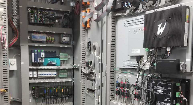
Figure 9: An inside view of a 15-kilovolt generator paralleling switchgear shows a portion of the control components and cabling required. Courtesy: IMEG Corp.[/caption]
Engineers should be aware of both the currently adopted codes and the latest editions of code to understand both the interpretation and the intent. As codes evolve, the intent tends to be clarified in each subsequent edition. The consistent theme of NFPA 110 is one of reliability, making a level 1 standby emergency power system as reliable and robust as possible to prevent harm or loss of life to building occupants.