Here are some considerations for designing piping systems for cooling distribution units (CDUs) within data centers.
Learning Objectives
- Learn about critical factors such as efficiency, reliability and integration with existing data center infrastructure to optimize thermal performance and energy use.
- Understand the function of a coolant distribution unit (CDU), which circulates chilled water to cooling equipment, maintaining optimal operating temperatures and enhancing system reliability.
- Explore the advanced thermal management strategies that accommodate high rack densities, ensuring effective heat dissipation and system stability in data centers.
Data center cooling insights
- Effective water-cooling solutions in high-density data centers rely on direct liquid cooling systems with coolant distribution units (CDUs) to regulate temperature and prevent overheating.
- To ensure reliability and efficiency, data centers must consider factors like redundancy, coolant selection and corrosion prevention when designing liquid cooling systems with CDUs.
There are several ways to implement water cooling solutions in high-density data centers. One method involves having the coolant circulate through cold plates that are affixed to processor modules and other high-powered electronic components within the rack.
The most prevalent approach for these water-cooling designs is to use a coolant distribution unit (CDU) positioned internally or externally to the high-density datacom rack called direct liquid cooling system.
A CDU is a crucial component in modern data centers and facilities that require efficient temperature management.
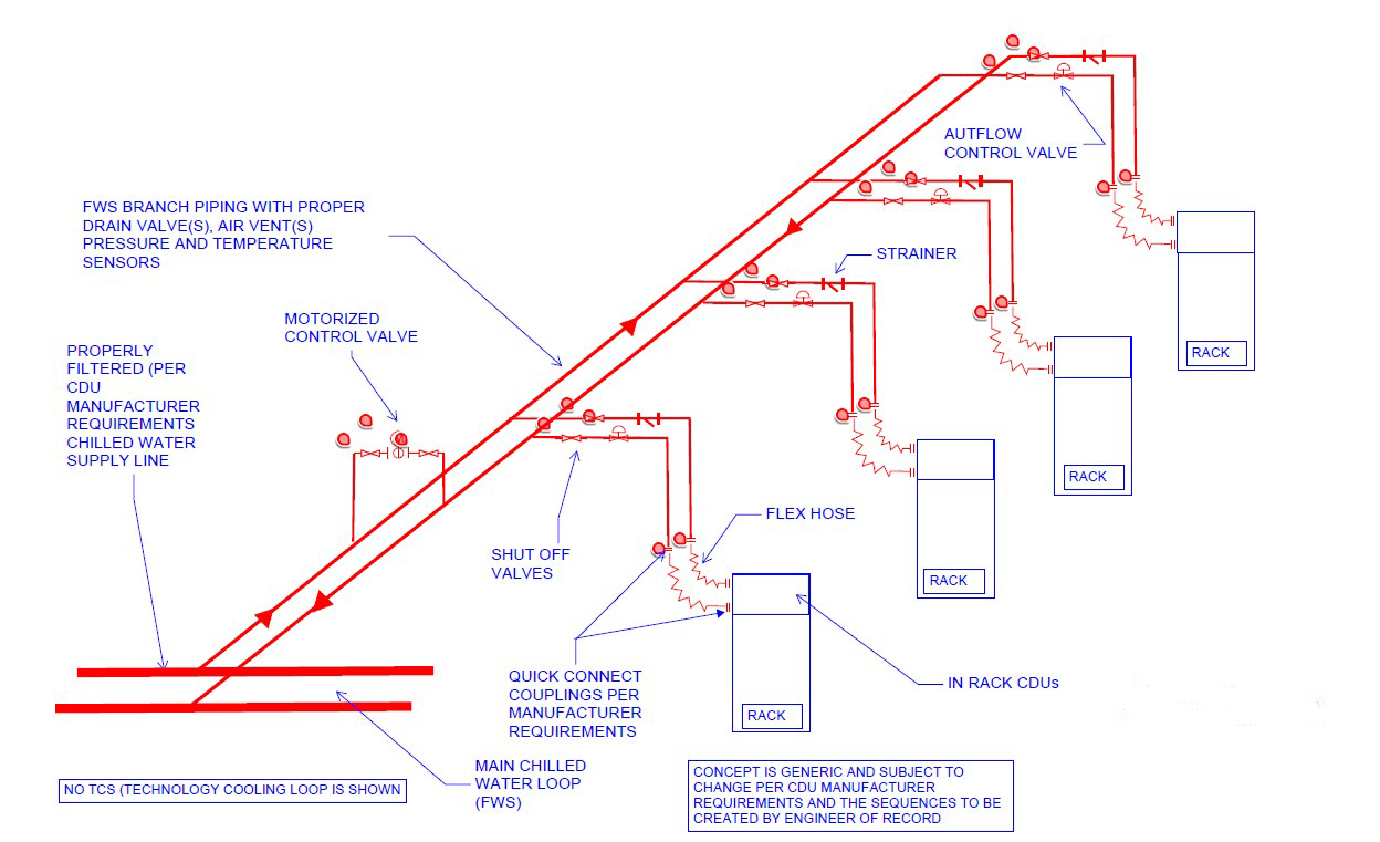
Direct liquid cooling establishes a sophisticated heat exchange loop consisting of pumps, piping, manifolds, fluid couplings and terminators, with the CDU serving as the central controller that facilitates heat exchange between the thermal control system (TCS) and the fluid working system (FWS). CDU is the brain of direct cooling systems on high-density data centers.
Key points about CDU capacities:
- Small scale (in-rack): 60 to 80 kilowatts (kW)
- Medium scale (in-row): 300 to 800 kW
- Large scale (high-performance data centers): 1 megawatt +
The CDU transfer heat from technology cooling system to facilities water system and circulates TCS coolant. CDUs can be integrated within individual racks to provide TCS coolant exclusively to that rack, or they can function as standalone units that distribute coolant across multiple racks.

To adapt to fluctuations of FWS temperatures and information technology equipment (ITE) heat loads, CDU employs sophisticated mechanisms such as bypass loops, proportional control valves and variable speed pumps.
TCS is governed by defined temperature bounds, with an upper and lower limit. The upper bound represents the maximum allowable TCS supply temperature at a specific flow rate to ensure adequate cooling for the connected ITE; exceeding this temperature may necessitate an increased flow rate and could result in overheating. Conversely, the lower bound often correlates with the dewpoint inside and around the rack. CDU is responsible for monitoring this to adjust the TCS temperature to at least 2°C above the room dewpoint, thereby averting condensation issues.
The CDUs must provide adequate cooling for plate and frame heat exchangers to meet lower temperature requirements. Warm water cooling can be advantageous due to the high heat capacity of the coolant, improving cooling efficiency.
However, the coolant inlet temperature must be determined based on the available thermal margin of critical components and the cooling efficiency of the cold plates.
CDU exchanges heat between TCS and FWS or TCS to air (radiator based). Inside the CDU, the liquid-to-liquid heat exchanger often features a flat plate construction, with plate spacing typically varying from 0.08 to 0.31 inches. Due to these dimensions, varying degrees of filtration are needed upstream of the CDU and within the FWS loop to ensure optimal performance.
Data center design elements
Mission critical facilities demand uninterrupted operation and performance. Some of the key factors that design engineer, contractor and facility management to pay attention are:
Redundancy: By incorporating redundant components — such as pumps, cooling loops and heat exchangers — these systems can maintain optimal cooling performance even in the event of a failure. This redundancy minimizes the risk of overheating, protects sensitive equipment and enhances overall system resilience.
Additionally, it allows for maintenance activities to be performed without disrupting cooling operations, thereby improving uptime and operational efficiency. Invest in redundancy, especially for critical systems, to ensure that if one component fails, there is a backup ready to take over, minimizing downtime.
Coolant selection: Selecting the appropriate coolant for liquid cooling involves several key factors, primarily focusing on thermal and hydrodynamic properties.
However, other significant considerations include toxicity, electrical conductivity, pH level, flammability, surface tension, potential for bacterial or algae growth and corrosion, all of which are crucial for ensuring reliable and long-term operation of liquid cooling systems. The coolant shall maintain consistent pressure and flow rates over time, along with corrosion prevention properties and compatibility with wet materials compared to other water-based coolants.
Particular care is needed, including thorough cleaning of tubes, manifolds and loops and corrosion inhibitors. Coolant selection needs to be done based on thermal properties, compatibility, environmental consideration, system design factors (i.e., flow rate, pressure, heat load), cost factors and safety considerations and surely needs to match with manufacturer requirements. It is recommended that small-scale tests with the selected coolant are performed to evaluate their performance under real operating conditions as part of the field testing.
Coolant velocity: According to ASHRAE TC 9.6 Thermal Guidelines for Liquid Cooled Data Processing Environment whitepaper during the design, there are limitations on coolant fluid velocity in pipes, recommending that it should not exceed 2.1 meters/second for pipe diameters larger than 3 inches. This limit is intended to minimize material erosion in the pipes.
Data center cooling fluids
TCS fluid chemistry is often proprietary in nature as selected/designed by the IT manufacturer. As such, chemical compatibility with the components in the TCS loop tends to be quite good and the fluid shows good stability over time within a completely closed environment.

However, issues can arise with water quality within the closed TCS loop. Foreign contaminants can be introduced over time as new ITE elements are introduced into the system.
As every site has different feed or makeup water quality available, the specifics of the treatment plan must be site specific. The challenges of each site FWS loop in terms of corrosion, fouling, scaling and microbial issues associated with the specific water chemistry and composition of the incoming water need to be comprehended. The facility should have water treatment expertise on staff or the facility should partner with a water treatment service provider to provide expertise on water chemistry and treatment. Ongoing water monitoring and water management is typically a part of the treatment regimen.
Debris is typically filtered at the CDUs using fine mesh filters (≤50 micrometers), but increased material in the coolant can lead to filter clogging, raising the risk of CDU pump failure or reduced flow rates. The TCS loop water quality requirements require a higher level of water quality than the FWS loop can provide.
Designing to mitigate corrosion
The lack of attention to corrosion in high-density data centers can lead to critical challenges that affect both operational efficiency and long-term sustainability. Incompatible materials in contact with the coolant can lead to galvanic corrosion. The chemistry of the coolant is influenced by the composition of wet materials, a challenge noted since the inception of liquid cooling. ASHRAE White Paper Water-Cooled Servers Coom Design, Components and Processes ASHRAE TC 9.6 2019 advises against using zinc, aluminum and brass containing more than 15% zinc, as well as non-stainless-steel iron.
While a higher concentration of propylene glycol is better for corrosion inhibition, a 25% concentration is preferred with deionized water in most cases.
Design to help reduce leakage
Leakage presents a significant risk for liquid-cooled systems, potentially causing severe damage to ITE and the data center environment. Detecting leaks — from the server level to the data center — is a high priority for maintaining smooth operations. Keeping fluid piping separate from IT and power equipment or cabling can mitigate leak risks.
Each rack should be equipped with isolation valves, allowing individual server isolation from the in-rack manifold for routine and emergency maintenance.
Designing systems that enable the shutdown of fluid flow to specific racks and servers allows maintenance to be conducted without disrupting critical operations. Additionally, tubing from the manifold to the server should feature dripless quick disconnects to prevent damage during server servicing.
Thermal control system is feasible only with fluid coupling architectures, each possessing unique characteristics that influence the volume flow rate and pressure within the TCS. Couplings equipped with shutoff mechanisms, such as dry-break connectors, are employed to prevent fluid spillage, with a maximum allowable liquid spillage within the server not exceeding 1 cubic centimeter.
When using flexible hoses, it is essential to incorporate additional clamps or ties to manage the hoses and minimize pressure drop. Flexible hoses provide advantages of cost efficiency, ease of maintenance and design simplification, particularly in applications involving multiple cold plates.
Conversely, when using rigid tubing or directly connecting the connector to a manifold or port, threaded terminations are typically preferred. For tapered pipe threads, the application of supplemental sealing paste during installation is often required to ensure a properly sealed interface.
When placing fluid connections near ITE, it is crucial to consider the vibrational factors that could affect long-term reliability. It is essential to strictly follow the recommended installation torque during setup to prevent any potential loosening over prolonged operational periods.
How to monitor cooling systems in data centers
Monitoring environmental conditions around liquid-cooled systems is essential for protecting ITE. Implementing intelligent flow monitoring and advanced leak detection apparatus within the cooling system will enhance proactive visibility in identifying harmful conditions, such as fluid leaks, humidity levels conducive to condensation and elevated fluid temperatures supplied directly to IT gear.

As heat densities rise, the system’s reaction time in responding to larger data events becomes increasingly important. Using advanced embedded controllers allows for flexible, programmatic interfaces that can collect nontraditional data sets, enhancing ITE protection and optimizing system energy efficiency.
Leak detection systems should be strategically placed throughout system components, reporting into or off a CDU and at critical locations along the piping system. These systems provide proactive alerts when fluid pressure drops at nodes, racks or data center levels, indicating a potential leak. They can also pinpoint the location of a leak, enabling teams to conduct controlled shutdowns of the CDU, servers and cooling systems, thus streamlining equipment troubleshooting and repair processes.
Liquid cooling systems require continuous monitoring and control, which may involve remote monitoring, conducting preventive maintenance, managing fluids and overseeing asset management.
How to ensure reliability in data center design
Mission critical facilities require continuous operation and optimal performance, with reliability being a crucial factor. How will the quality of a system product evolve over time? When is it likely to fail? Reliability is defined as the probability that a product, system or service will adequately perform its intended function for a specified duration or operate without failure in a defined environment.
Reliability can be measured with mean time to failure (MTTF). MTTF of a component is calculated by summing the lengths of the operational periods and dividing by the number of observed failures.
MTTF = ∑ (start of downtime − start of uptime)/number of failures.
Although liquid cooling has been around since the 1960s, advancements in materials, systems and equipment reliability are still in the research phase.
In many cases, implementations have outpaced research, understanding failures in short-term system evolvements due to the rapid evolution of IT. This presents a real risk for everyone involved in the process.
It is essential to recognize that common design and operation key points in the piping systems associated with CDUs often stem from critical conditions that require thorough evaluation and proactive management. Issues such as inadequate system design, improper installation practices and insufficient operational oversight can lead to significant operational disruptions and costly repairs.
Therefore, a comprehensive approach that emphasizes meticulous design planning, rigorous quality control during construction and ongoing monitoring in operation is vital. By addressing these key points with diligence and foresight, engineers can ensure the reliability and efficiency of CDU piping systems, supporting the optimal performance of high-density data centers.