Meeting ASHRAE 62.1 requirements in VAV systems presents unique challenges, as fluctuating airflow, varying occupancy loads and system diversity.
Learning objectives
- Understand the key ASHRAE 62.1 requirements as they apply to variable air volume (VAV) systems, including zone air distribution effectiveness and system ventilation efficiency.
- Identify the challenges VAV systems present for maintaining compliance, such as varying airflow rates, occupancy diversity and their impact on outdoor air delivery.
- Apply strategies to achieve compliance with VAV design, including outdoor air calculation methods and balance techniques to ensure stable ventilation performance.
VAV insights
- A VAV system enhances commercial energy efficiency and comfort by modulating airflow to meet specific zone loads while maintaining a constant supply air temperature.
- To remain compliant with ventilation standards, a VAV system must be carefully designed to ensure that minimum outdoor air requirements are met across all zones even as supply volumes fluctuate.
Variable air volume (VAV) systems are among the most widely used air distribution strategies in commercial heating, ventilation and air conditioning (HVAC) design because of their flexibility, energy efficiency and compatibility with modern ventilation standards such as ASHRAE Standard 62.1: Ventilation and Acceptable Indoor Air Quality.

Understanding how VAV systems are defined and applied, particularly in comparison to constant air volume (CAV) systems, is essential for achieving code-compliant and high-performance designs.
The 2024 ASHRAE Handbook—HVAC Systems and Equipment provides extensive guidance on air distribution approaches. For example, Chapter 2, Section 2.10 “Single-Zone VAV Systems” gives an in-depth discussion of single-zone VAV systems, outlining their advantages and disadvantages, recommended control sequences, terminal unit options and key application considerations.
This foundational material helps designers determine when a VAV approach is appropriate, how it should be integrated with ventilation strategies and which operational characteristics most strongly influence system performance. It also clarifies how single-zone VAV differs from multizone configurations, particularly in terms of controls and energy-saving potential. By establishing these fundamentals early in the chapter, the handbook provides a framework designers can apply when approaching more advanced VAV system types.
A common misconception is that a VAV system automatically means “VAV boxes.” While VAV boxes are typically in multizone systems, they are not required for all VAV applications. In a single-zone VAV system, one air handling unit (AHU) serves a single thermal zone. Airflow from the AHU is modulated to match the load of the space, with the cooling and heating coil outputs simultaneously adjusted to meet the required thermal conditions. No downstream VAV terminal units are required because only one zone is being controlled.
In this configuration, the AHU’s supply fan speed varies to meet demand, with cooling and heating coil output adjusted accordingly. The system is still considered a VAV system because the airflow changes over time, even though no terminal boxes are present.
In a multizone VAV configuration, a single central AHU serves multiple thermal zones, each equipped with its own terminal unit (VAV box) that independently modulates airflow in response to a space temperature sensor. Manufacturers provide a range of terminal-unit types — including cooling-only boxes, electric or hot-water reheat boxes and fan-powered VAV units — to accommodate different design and comfort requirements.
Additional features to consider are insulation, sound attenuation and control options. This arrangement enables precise zone-level temperature control and represents the most common VAV system configuration used in commercial office buildings, educational facilities and healthcare environments.
The key distinction between VAV and CAV systems is how they respond to load changes. A CAV system delivers a fixed airflow rate to a space. Depending on the design, a CAV system may respond to load changes by modulating the supply air temperature or, in many cases, by cycling the unit on and off. In practice, operating schedules can cycle cooling but not ventilation. The fans continue running and outdoor air (OA) remains at its set level, since it’s not acceptable for ventilation to shut off in commercial spaces.
A typical residential air conditioning unit is a good example of a CAV system: The fan operates at a steady speed and delivers a constant volume of air, while the equipment cycles on and off based on the thermostat — or, in some cases, humidity control — to maintain the desired conditions. Many newer high‑efficiency residential systems, however, use variable‑speed fans that modulate airflow.
A VAV system, by contrast, keeps the supply air temperature relatively constant and varies only the airflow rate to meet the space’s changing load. At peak cooling demand, the system delivers maximum airflow; as the load decreases, it reduces the airflow accordingly. This approach offers several advantages, particularly in relation to modern energy codes and ventilation standards. Lowering airflow significantly reduces fan energy consumption, improving overall efficiency.
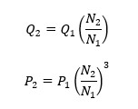
Referencing the affinity laws, a 25% reduction in airflow (Q) produces a 25% reduction in fan speed (N), which then leads to a 42.2% reduction in overall power consumption (P). In multizone buildings, VAV systems also allow each space to respond independently to its own load profile, which enhances comfort and provides more precise environmental control (see Figure 1).
VAV systems rely on the ability to continuously modulate supply fan speed in response to changing duct static pressure. As VAV dampers open and close, the system pressure profile shifts and the supply fan adjusts its speed to maintain the target setpoint. Traditionally, this modulation was achieved using variable frequency drives (VFDs). Electronically commutated motors now provide the same dynamic speed control without requiring a separate VFD, making fan turndown more efficient and streamlined. By varying fan speed rather than throttling airflow, the system significantly reduces energy use because the fan’s power draw drops sharply as speed decreases. This results in substantial savings during part-load operation, which represents most building operations.
Based on 2025 ASHRAE Handbook Fundamentals, Chapter 14 “Climatic Design Conditions,” HVAC systems are typically sized to meet 1% cooling and 99% heating design conditions, meaning buildings operate below peak load for well over 90% of the year. Due to this, equipment spends most of its life modulating part load rather than running at full capacity, making part-load efficiency far more impactful than peak performance.
In addition to improving energy performance, variable‑speed operation allows the system to better match outdoor air delivery to actual demand. This stable, demand-driven airflow helps maintain proper ventilation rates across all zones, supporting compliance with ASHRAE 62.1 even as occupancy and thermal loads fluctuate.
In addition to central fan-level control, VAV systems rely on zone-level strategies to maintain comfort and efficiency across the building. In multizone applications, dampers regulate the volume of air delivered to each zone (see Figure 2). Beyond simple flow control, these dampers play a critical role in maintaining proper ventilation rates under varying load conditions.
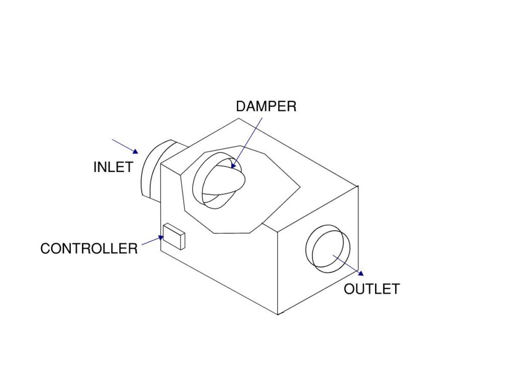
As zone demands fluctuate, the damper position directly influences how much OA is ultimately distributed to each space, making accurate damper operation essential for meeting the minimum ventilation requirements prescribed by ASHRAE 62.1, Chapter 6.2 “Ventilation Rate Procedure.“ Properly calibrated and responsive dampers help prevent underventilation during low-load periods, support stable pressurization and ensure that the system’s ventilation strategy remains effective across the full range of VAV operations.
Calibration typically includes setting the damper’s minimum and maximum positions to match the required airflow rates verified through testing and balancing. A responsive damper precisely tracks control signals, opening or closing quickly and proportionally, so that commanded airflow changes are delivered without delay.
Codes and standards for mechanical systems
ASHRAE 62.1 sets the technical benchmark, but the mechanical code is what most jurisdictions adopt and enforce for mandatory requirements. Depending on the state, this may be a statewide code or a more restrictive municipal amendments, typically based on the International Mechanical Code (IMC). Designers often follow the latest ASHRAE guidance for best practice, and compliance is ultimately judged against the version of the mechanical code adopted by the authority having jurisdiction.
ASHRAE 62.1 defines which spaces require dedicated exhaust and the minimum exhaust rates, as outlined in ASHRAE 62.1, Table 6-2 “Minimum Exhaust Rates.” This standard also establishes the minimum ventilation rates necessary to maintain acceptable indoor air quality (IAQ) in occupied spaces, as expressed in Table 6-1 “Minimum Ventilation Rates in Breathing Zone.”
In the context of ASHRAE 62.1 and mechanical codes, “ventilation” specifically refers to OA brought into the building — not supply, return or exhaust airflow. ASHRAE 62.1 specifies the outdoor airflow that must be delivered to each zone based on both occupancy and floor area, forming the basis of any compliant ventilation design.
Exhaust air serves two primary functions in buildings: removing contaminants at the source and maintaining required pressure relationships. These functions are especially critical between adjacent spaces to prevent cross-contamination — for example, ensuring that laboratory areas do not negatively impact surrounding zones or vice versa.
In VAV systems, these functions become more complex because supply airflow varies with load. As the supply air modulates, the exhaust system must be designed and controlled to ensure that contaminant removal and pressure control remain consistent. Without proper coordination, pressure relationships can shift as the supply airflow turns down, potentially compromising containment.
ASHRAE 62.1 establishes minimum exhaust airflow rates for many space types. These rates are typically expressed as cubic feet per minute (cfm) per square foot, or cfm per unit. For example, toilet rooms generally require 50 to 70 cfm per fixture, while janitor closets require approximately 1.0 cfm per square foot. Maintaining these minimum exhaust rates during the design process is essential to ensure that contaminants are removed at a predictable rate, independent of the supply system’s VAV turndown.
In VAV systems, these requirements intersect directly with the system’s variable airflow nature. Because supply airflow modulates in response to changing loads, the ventilation strategy must ensure that every zone continues to receive its required minimum OA under all operating conditions, not only during peak cooling when airflow is highest.
In multizone VAV systems, the AHU must supply enough system-level OA to satisfy the “critical” zone — the zone that, at any given operating condition, requires the highest proportion of OA relative to its supply airflow. As individual zone airflows modulate changing loads, the critical zone can shift throughout the day, directly influencing the OA intake required at the system level.
To manage this variability, designers must calculate each zone’s OA requirement, determine the system’s ventilation efficiency and evaluate performance under both peak and part‑load conditions. When implemented correctly, this approach maintains compliance with ASHRAE 62.1 while optimizing energy use, ensuring that IAQ, pressure relationships and overall system performance remain stable even as VAV boxes continually adjust across the building.
Controlling VAV systems: key challenges and solutions
There are challenges associated with both single-zone and multizone variable volume systems. To combat this, different factors must be considered when calculating required airflows throughout the system. Ventilation calculations can be performed with ASHRAE supplied spreadsheets or vendor software, which incorporate ASHRAE 62.1 ventilation standards into overall system sizing. When using vendor software, results should be verified against ASHRAE 62.1. Zone air distribution effectiveness (Ez) is one factor that must be considered for OA requirements. Ez is how well a system will dilute contaminants within a breathing zone.
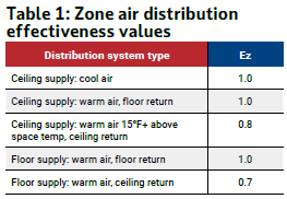
ASHRAE 62.1, Section 6 “Procedures” lists various air delivery methods and the corresponding Ez values, depending on how air is distributed to the zones. Three different configuration types are:
- Well-mixed air distribution systems (see Table 1)
- Stratified air distribution systems
- Personalized ventilation systems
The stratified air and personalized ventilation systems both have potential Ez values greater than 1, which in turn reduce the OA requirement. The well-mixed systems will have Ez values less than or equal to 1, which can increase the required OA. As seen in Table 1, the instances that provide Ez values less than 1 are those that return air to the ceiling during heating mode. Removing potential contaminants from the breathing zone is less effective because hot air rises to the top of the space and the air in the breathing zone does not get mixed well due to the supply being provided at the top as well.
According to ASHRAE 62.1, the breathing zone is a portion of occupiable space located between 3 and 72 inches above the floor and at least 2 feet away from walls or fixed air conditioning equipment. The most effective way to prevent air from bypassing this zone is to use a floor‑level return.
However, that approach isn’t always practical, especially in buildings without basements, which is common in many Southern regions.
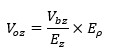
For the OA design, the Ez value must be divided by the ASHRAE 62.1 minimum OA requirement (Vbz) and then multiplied by a correction factor for air density (Eρ, see Figure 3), resulting in a corrected OA value (Voz). ASHRAE 62.1, Table 6-5 “Air Density Correction Factor” tabulates various correction factors for air density depending on how high the OA intake is located above sea level. This equation is how one could potentially get an increased value for well-mixed distribution-type systems with a ceiling return.
Normative Appendix C of ASHRAE 62.1 demonstrates an alternate method for calculating zone air distribution effectiveness and may produce either higher or lower OA requirements than using the calculations in Figure 3, which would only be used to justify using an Ez value that results in a lower minimum OA flow rate. This method considers average contaminant concentrations in the breathing zone, at supply and at exhaust. This method requires the use of computational fluid dynamics modeling software.
An example where one would use Normative Appendix C would be with U.S. Green Building Council LEED projects, which strive for much higher energy efficiency so more optimized calculations can help gain more points toward the project’s goals.
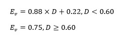
Multizone systems are more of a challenge when it comes to VAV systems, as there may be varying airflow rates required throughout the system due to occupant diversity (D). Occupant diversity considers how the number of people across zones of a system will vary. This can be due to differences in space type or time of day — for example, the peak people load may not be the same in an office space versus a breakroom at one time. Occupant diversity is then used alongside system ventilation efficiency to determine the adjusted OA that is required for the system. System ventilation efficiency (Ev) is how well a system delivers air to each zone and depends on the occupant diversity (see Figure 4).
Like zone air distribution effectiveness, this Ev value is then divided by the ASHRAE 62.1 ventilation requirement to ultimately determine the adjusted airflow needed for the system. Higher occupant diversity results in lower corrected OA values, while lower occupant diversity results in higher corrected OA values.
Another method to determine system ventilation efficiency for multiple zones is to use Normative Appendix A of ASHRAE 62.1. This may provide a more restrictive result and the higher OA requirement of the two would be used.
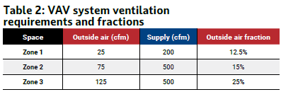
To determine the amount of OA provided to a single zone within a multizone VAV system, the Ez value for each zone is calculated separately using Table 1. This will provide a corrected amount of OA required by that individual space. These corrected OA values are then compared against the system’s designed supply air rates to identify the zone with the highest fraction, which will be considered the most critical zone.
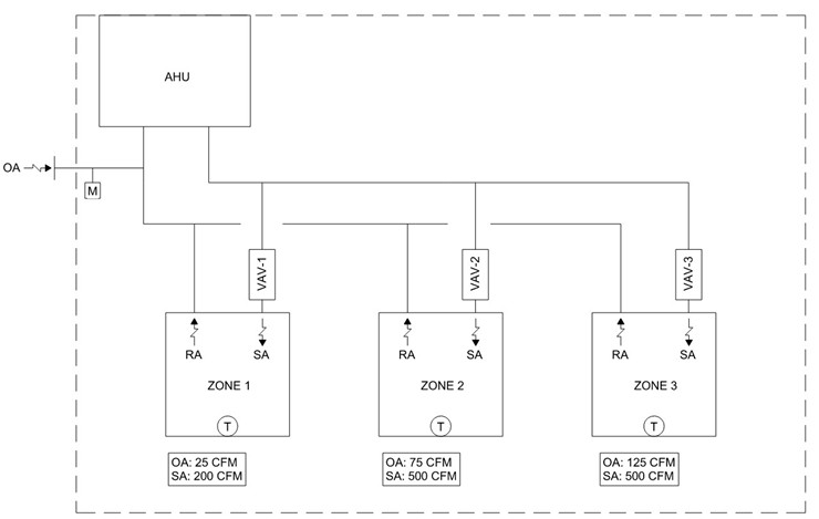
The supply air is the peak supply to each VAV box, while the OA values are the minimum required per ASHRAE 62.1 (see Figure 5). Table 2 presents these values with their associated OA fractions.
Zone 3 would be the critical zone, as it has the highest fraction of required OA relative to the supply air (see Table 2). Therefore, the system must be designed to provide at least that fraction of OA to the whole system.
Because multizone VAV systems mix all OA at the unit’s return rather than ducting it separately to each space, there is no guarantee that the amount of air required for the critical zone would get there if this OA fraction were not considered. If the OA fraction is potentially too high, this can be reduced by providing more supply air to that individual zone, thereby reducing both the OA fraction and the overall system OA fraction (with the understanding that another zone may then become the new critical zone).
After system construction is complete, OA should be field-tested to ensure that the breathing zones throughout the system receive the designed amount of ventilation. This includes minimum OA percentages as well as minimum and peak SA to VAV boxes. If spaces are not receiving the intended amount of ventilation, careful investigation into the functionality of physical components or controls must be carried out.
The amount of OA pulled into the system is controlled by motor-operated dampers that can be anywhere from fully open to fully closed depending on the zone needs. This, along with other VAV box components, is controlled through a direct digital control system, which helps to automate any functions required to maintain IAQ during occupied times.