This article discusses design requirements of NFPA 110 (2016) and how it applies to emergency and standby power systems in mission critical facilities. It also reviews other relevant codes, such as NEC (2017), NFPA 99 (2018), and IBC (2015), and discusses how they complement NFPA 110.
Learning Objectives
- Understand NFPA 110-2016 design requirements.
- Learn about other codes, such as NFPA 70: National Electrical Code (NEC), NFPA 99, and IBC, and how they complement NFPA 110.
- Know how to apply these design requirements to mission critical facilities.
This article has been peer-reviewed.
The scope of NFPA 110-2016: Standard for Emergency and Standby Power Systems covers the performance of emergency and standby power systems that provide an alternative power source of electrical power to loads in buildings in the event the primary power source fails. The performance of the standby and emergency power systems is a complete lifecycle that starts with conceptual planning and design and extends to cover installation, operation, testing, commissioning, and maintenance.
NFPA 110 is not intended to be a design manual, as it only applies to the performance of emergency and standby power systems. However, there are many inherent design considerations that consulting and specifying engineers should be aware of and know how to apply when designing emergency and standby power systems for mission critical facilities.
There are two definitions that are important in understanding NFPA 110. The emergency power supply (EPS) is the source of electric power, such as a diesel generator. The emergency power supply system (EPSS) includes, in addition to the EPS, conductor-disconnecting means, overcurrent protective devices (OCPD), transfer switches, and all controls and support devices up to and including the load terminals of the transfer equipment.
NFPA 110 recognizes two types of systems: Level 1 and Level 2. A Level 1 system is installed where failure of the equipment or system could result in loss of human life or serious injuries. Examples of a Level 1 system are illumination to the means of egress, fire alarm system, fire pumps, smoke-ventilation systems, lights and selected receptacles in hospital operating rooms, and other critical and general patient-care spaces. Level 2 systems are less critical to human life, but when stopped could create hazards or hamper rescue or firefighting operations. Examples of a Level 2 system include heating and cooling systems, ventilation, elevators, and domestic-water and sewage-ejection pumps.
The following is a discussion of major design considerations that apply to building electrical systems. Design issues related to fuel and mechanical systems are not discussed in this article.
Chapter 5.6.5: Control functions
NFPA 110 requires a remote manual-stop station located outside the room housing the alternate source prime mover. In addition, shutdown controls are required to be located in the generator control panel that is typically mounted on the generator itself or within the generator room. For generators located outdoors, the manual shutdown should be located external to the enclosure and should be appropriately identified and labeled. This requirement is in line with NFPA 70-2017: National Electrical Code (NEC), Article 445.18, which requires two means of shutdown to the prime mover for generators greater than 15 kW. This means of shutdown shall disconnect and disable all start start-control circuits and initiate a shutdown mechanism that requires a mechanical reset (see Figure 1).
Chapter 5.6.6: Remote controls and alarms
NFPA 110 requires two types of annunciation for Level 1 EPS: local annunciation and facility facility-remote annunciation, or local annunciation and network-remote annunciation. Local annunciation is located on the generator itself or within the same generator room. Facility remote annunciation is located onsite, usually at an engineering-control station or facility-maintenance station. Network remote annunciation is located offsite. For Level 2 EPS, only local annunciation is required.
Alarm and annunciation must be powered by the prime mover’s starting battery or from an alternate power source, such as a storage battery, an uninterruptible power supply (UPS), or a branch circuit supplied by the EPSS. Section 911 of the International Building Code (IBC) requires that generator and transfer switch annunciation be provided in fire command centers (FCC) where an FCC is required in facilities such as high-rise buildings. NFPA 99-2018: Health Care Facilities Code, Chapter 6.7.1.2.15, requires the alarm annunciator to be hard-wired. A building management system (BMS) or an electrical power and monitoring system (EPMS) is permitted to be used to supplement the alarm annunciator but is not permitted to substitute it per NFPA 99, Chapter 6.7.1.2.15.9.
Chapter 6.1.6: Transfer switch equipment
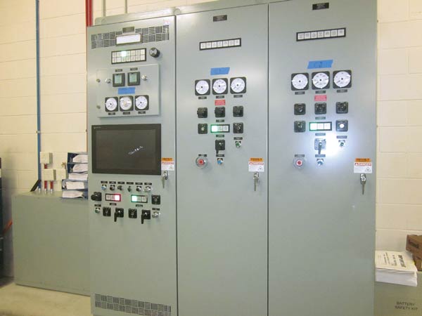
Transfer switches for Level 1 and Level 2 emergency and standby power systems need to be tested and listed for emergency purposes. In applications such as large campus facilities with multiple buildings and central generators where there might be a need to use medium-voltage transfer schemes, it is permitted to use electrically interlocked medium-voltage circuit breakers instead of complete factory-assembled transfer switches for loads other than life safety, emergency, or critical-branch (see Figure 2).
Chapter 6.2.3: Interlocking
NFPA 110 requires mechanical interlocking or an approved alternative method to prevent the inadvertent interconnection of the primary power supply and the EPS, or any two separate sources of power. In some applications, closed-transition switching is used, which allows momentary paralleling of generators with the utility. An open-transition switching mechanism is a break-before-make sequence. Switches operate very quickly, but power is interrupted for approximately 40 milliseconds. Open-transition switches are suitable for a wide range of applications where momentary power interruptions are acceptable.
Closed-transition switching, on the other hand, operates in a make-before-break mechanism that momentarily parallels the two power sources. The switching sequence occurs in less than 100 milliseconds to avoid impacting utility systems. Some utilities allow more time but require special protective relays to ensure safe paralleling of the EPS and utility power. Closed-transition switching could be used to supply critical-branch loads in hospital operating rooms, where power interruption even for a few milliseconds is not acceptable. The approval of the utility company and the authority having jurisdiction (AHJ) is needed for closed-transition switching.
Chapter 6.2.15: Isolation of neutral conductors
The power distribution systems must have provision to ensure continuity, transfer, and isolation of the primary and the EPS neutral where separately derived systems, such as generator systems, are used. The system-grounding conductors for a separately derived system should be grounded at only one point and ahead of any system-disconnecting means. Grounding conductors must be arranged so that objectionable stray neutral currents will not exist and ground-fault currents will flow effectively to assure effective operation of OCPDs to protect personnel from electrical shocks.
NEC, Article 230.95, requires ground-fault protection on solidly grounded systems having line-to-ground voltage larger than 150 V (for example, 480 V/277 Y) and rated 1,000 amp or more. It is to be noted that ground-fault protection with automatic disconnecting means shall not be required at the alternate source of emergency power system (generator); only ground-fault indication (alarms) shall be provided in accordance with NEC, Articles 700.31 and 700.6(D).
Ground faults are currents that flow from a phase conductor to ground. They can occur as arcs across air gaps. Because ground-fault currents often occur at levels that are insufficient to trip a circuit OCPD, the fault can persist and cause severe damage to equipment. Means or devices would be needed to ensure proper ground-fault sensing and tripping to protect equipment. Correct grounding in standby systems that are solidly grounded is a function of the transfer switch configuration (3-pole/solid neutral or 4-pole/switched neutral). If generators are configured as a separately derived power source (4-pole transfer switches), then the neutral at the generator would have to be bonded to ground, and a ground conductor would need to be connected to the grounding electrode system. If the generator neutral connects to a service-supplied grounded neutral, typical at the neutral terminal of a 3-pole transfer switch, then the generator neutral should not be grounded at the generator.
Chapter 6.3: Load switching/load shedding
When two or more generators are paralleled for emergency power, the paralleled system must be arranged to prevent the connection of EPS-damaging loads. The sequence of transferring loads to the EPS starts with the first-priority loads, such as emergency loads (NEC, Article 700), followed by legally required standby loads (NEC, Article 701), and lastly, the optional standby loads (NEC, Article 702). The loads must be switched to the emergency bus upon sensing the availability of emergency power. Power must be restored to emergency loads within 10 seconds, and to legally required standby loads within 60 seconds.
Each time an additional generator in a paralleled EPS configuration is connected to the bus, a remaining load shall be connected in order of priority until all standby loads are connected to the bus. The sequence of transferring loads to the EPS in a hospital starts with the life safety-branch loads (NEC, Article 517.33) and critical-branch loads (NEC, Article 517.34), then followed by the equipment-branch loads (NEC, Article 517.35). The system shall also be specified so that, upon failure of one (or more) generator(s) or associated power distribution or protective device(s), the connected loads are automatically reduced (shed off) in reverse order of load switching. Connecting loads in sequence with proper time delays while staying within the code’s requirements for restoration time reduces starting requirements on the EPS and could potentially reduce the size of generators. A few seconds of time delays between load steps would also help generators to stabilize voltage and frequency (see Table).
Chapter 6.5: Protection
NFPA 110 requires proper OCPD selective coordination on the essential electrical system to optimize selective tripping at fault conditions. A short-circuit and selective-coordination study would need to be performed by the specifying engineer to determine the maximum available short-circuit current at the service and all switchboards, panels, and transfer switches. Per NEC, selective coordination is required for the full range of available overcurrents (overload, short circuit, and ground faults) and for the full range of OCPD opening times associated with those overcurrents. This requirement is modified by both NEC, Article 517.30.G, and NFPA 99, Chapter 6.7.2.2.2.1, applicable to health care facilities, where the OCPDs need to be coordinated for faults that extend beyond 0.1 second only.
Chapter 7.1.2: Installation and environmental considerations
The EPS and the EPSS should be protected from floods, fire, vandalism, wind, earthquakes, lightning, and other environmental hazards. IBC, Section 2702.1.7, requires essential electrical systems to be installed in accordance with American Society of Civil Engineers (ASCE) 24: Flood Resistant Design and Construction for Group I-2 occupancies, such as hospitals and nursing homes. ASCE, Chapter 7, has specific requirements for minimum elevations of electrical equipment above the base flood elevation of a site’s geographic location.
A good practice is to avoid locating the EPSS equipment (including generators, essential switchgear, and transfer switches) in basements subject to flooding. In seismic-risk areas, seismic bracing for the EPS and EPSS equipment and any associated fuel-supply system should be considered. Protection against lightning strikes also should be considered for EPS equipment located outdoors. Surge arresters at medium-voltage equipment and surge-protection devices at low-voltage distribution equipment should be provided at panels serving sensitive electronic equipment and life safety loads, to protect circuits against voltage surges from lightning strikes in the vicinity of power lines or as a result of switching inductive circuits.
Chapter 7.2: Location
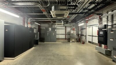
The EPS shall be installed in a separate room for Level 1 installation. Furthermore, the EPS room shall be separated from the rest of the building by 2-hour fire-resistance walls. Although NFPA 110 allows the EPSS equipment to be installed in the EPS room, it does not permit any other equipment-except those that serve this space-to be in the EPS room. NFPA 110, Chapter 7.2.3, requires Level 1 EPSS equipment is not be installed in the same room with the normal service equipment where the service equipment is rated higher than 150 V to ground and equal to or greater than 1,000 amps. NFPA 110 does not restrict Level 2 EPSS equipment from being located in the same rooms with Level 1 equipment (see Figure 3).
Chapter 7.12: Distribution
The electrical distribution system would need to comply with the NEC. For health care facilities, the EPSS would need to comply with NFPA 99. NFPA 99, Chapter 6.7.1.2.4.1, requires that Type 1 and Type 2 essential electrical system (EES) power sources be classified as Type 10, Class X, Level 1 generator sets per NFPA 110. The “Type” in NFPA 110 is the maximum time in seconds that the EPSS will permit the load terminals of the transfer switches to be without power. The “Class” in NFPA 110 is the maximum time in hours for which the EPSS is designed to operate at its rated load without being refueled. A Type 10 means that power must be restored within 10 seconds, but the amount of time the EPSS is required to run without refueling (Class X) is not defined in NFPA 110 and needs to be as required by other codes or by the AHJ.
The EES defined in NEC and NFPA 99 extends well past the terminals of the EPSS transfer switches defined in NFPA 110, as it includes, in addition to the EPS and EPSS, all distribution equipment downstream to the load terminals of transfer switches to ensure continuity of power to maintain health care facility operations during a power outage. The wiring between the EPS output terminals and the first distribution (OCPD) should be kept at a minimal distance for additional system reliability and safety. Underground conductors that are part of the EPSS distribution should be installed in concrete-encased duct banks. Per NEC, Article 700.10.D.1, feeder conductors that are a part of the EPSS, emergency systems in certain occupancies such as hospitals, must be protected against fire by being installed in spaces that are fully protected by an automatic fire suppression system, installed encased in a minimum of 2 in. of concrete, or be a UL-listed fire-resistive cable system or electrical-circuit protective system (see Figure 4).
All ac-powered support equipment necessary for the operation of the EPS must be supplied from the load side of the transfer switches or the output terminals of the EPS ahead of the main EPS OCPD to ensure continuity of the EPSS operation. NEC, Article 517.33.F, applicable to Type 1 health care facilities, requires that generators’ fuel-transfer pumps, ventilation fans, electrically operated louvers, controls, cooling, and heating systems to be connected to the life safety branch of the essential electrical system or to the generator terminals.
There are many design requirements for emergency and standby power systems addressed in a number of NFPA standards and codes. These design requirements extend to cover the power distribution system including transfer switches, alternative emergency sources, controls, overcurrent protection, location, and environmental conditions. Design engineers should conduct code research at the start of the design phase to identify which codes and standards apply to the project at hand, how these codes overlap, and how they impact the power distribution system in mission critical facilities.