By fully understanding BIM, identifying how it will be used on a project, and adding additional modeling tools to maximize its utility, design and construction teams can maximize project delivery.
Learning objectives
- Understand the differences between a traditional Revit building model and BIM.
- Explain the ways in which different project delivery methods can impact using BIM.
- Explore the benefits of add-on software that is available to expand the power of BIM.
Owners, consultants, and contractors often agree that BIM is the right approach for coordinating a project from design through operation. But maximizing the integration of this powerful tool requires a mutual understanding of what BIM is and how the design and construction team intends to work within the model.
Some teams use an Autodesk Revit 3-D model as a coordination tool and depend on conventional drawings of elevations and generic content that is not reflective of the actual conditions. A BIM, on the other hand, includes information linked to model elements to provide a deeper level of project-specific design data, specifications, and even operation and maintenance procedures. This allows design, construction, and facility personnel to delve into the model and use it as a tool that reflects the building’s true design. Another useful feature of a 3-D model is that elevations and sections can be created and viewed at any location in the model.
With a Revit delivery, the model to coordinate disciplines will show the building’s structural components elements, and ceiling heights, but the elevation elements may or may not be shown. Some disciplines only use elevations as supplementary drafting detail of the model. This can cause omissions or clashes if not clearly communicated upfront about the expectations of how the model is built. Coordination reviews require toggling between many detail sheets and elevations to see the entire scope of the model. Chasing these references makes it harder for the design team, the constructors, and owner to see and understand the design intent. Incorrectly tagged references—a common occurrence—lead to misleading design intent altogether. Additionally, when miscellaneous metals are not included on the base model, coordinating ductwork and risers becomes much more difficult.
Conversely, with BIM, the wall elevations are linked from the model so all of the content is visible to the rest of the team and is located in one place. This method increases efficiency, ensures the work is integrated into the design, and makes it easier for the design team, constructors, and owner to review design intent on the screen without toggling between many sheets. In addition, mechanical, electrical, and technology in-wall devices can be placed more accurately during design because the model also includes furniture, casework, and other architectural details to more clearly depict elevations, device orientations, and design intent.
Delivery method affects BIM
The project delivery method also can have an impact on the characteristics and intended use of BIM. The BIM deliverable may take a different form in a design-bid-build project versus a design-build project. Yet another version of the model may emerge when integrated project delivery (IPD) is used, in which all stakeholders cooperatively work through a project seeking speed to market, constructibility, and cost control-and all hold some form of contractual accountability.
Design-bid-build projects
In a design-bid-build project, disciplines design with a BIM platform, using competitively biddable construction documents that incorporate the owner’s program requirements, which are developed through a series of user group meetings. The intent is to provide a design based on the project budget, potentially with milestone cost checks from a third party to verify the project is staying within the construction budget. The design of the technical components with this model is based on the judgment of the design professionals and input from the owner. This model will typically only show basic design intent and will assign the constructors the task of enhancing the base model into a coordinated and integrated delivery package for field fabrication.
Design-build projects
In a design-build project, the design team is usually assigned to work under a construction manager. Within this deliverable, the owner, constructors, and design team are all active design participants during the construction document process. Owner user group meetings still occur during the design development, but with this deliverable model, the constructors can provide real-time feedback about decisions that can cause construction budget issues. Options can be presented to maintain design intent, but they might use different materials or means and methods to maintain the project budget. Therefore, the model’s specifications are collaboratively modified to reflect the changes and maintain model integration. With this model, major construction subcontractors are brought in early so the bidding time is reduced and the owner can make the decisions to proceed faster, which can save several weeks in the bidding and construction period.
IPD projects
An IPD project is similar to the design-build process except that a construction budget is set at the beginning and is contractually binding. All parties have a financial stake in the project’s success, from the construction budget to the construction time frame. As this BIM deliverable has financial incentives as well as penalties, it promotes cooperation and collaboration from all parties to provide a design that is integrated, at or under budget, and able to forecast unforeseen circumstances that often slow down construction.
Regardless of the project delivery method, architects, engineers, and specialty consultants can optimize their ability to efficiently meet the project goals by working within a shared and mutually understood BIM. Being able to share these models frequently or in real time enhances integration and communication, allowing the design team to correct their course early instead of later in design or during construction.
Starting a project with BIM
Prior to beginning a BIM, massings/stackings, system design concepts, and space allocations must be developed based on programmatic information, the budget, and preliminary meetings with the client. These early concepts are typically more high-level sketches than drawings. (See Figure 1 for an example of a high-level blocking diagram.)
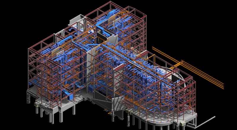
With the program, budget, and early design concepts in hand, the team can begin developing the BIM, which traditionally merges the design of the architect with the engineers’ design for structural, technology, and mechanical, electrical, plumbing, and fire protection (MEP/FP) systems. A BIM kickoff meeting should be held at this point, so all stakeholders can clearly define the expectations of what the model will provide to whom and at what stage. As each discipline adds their content to the model, it is quickly determined where building constraints will require further thought and design adjustments.
Figure 4: A snipping tool was used to capture this area of a collaborative drawing. Courtesy: IMEG Corp.[/caption]
With a typical Revit deliverable, it is not common for the design team to model duct and piping systems with hangars and insulation shown, nor is it common for the design team to model conduit under 2 in. or to show in-wall conduit or piping systems. In addition, the recorded set of documents is typically assigned to the constructors to provide. (This record set includes a fully coordinated model indicating all raceways, ducts, and pipes in the walls, as well as the overhead and below-floor distribution.) With BIM, however, collaboration between the design team and constructor can setup the model so the approved shop drawings can be linked to the equipment, with a click of the components’ opening menus for operation and maintenance manuals, shop drawings, and troubleshooting guides.
Expanding on BIM with additional tools
Add-on software makes it even easier to illustrate issues within an integrated model. Tools are being developed continuously. For example, snipping tools can be used to capture an area; save and add notes to fully describe the question, issue, or condition; and then email the clip to the design team (see Figure 4).
Lighting software tools can be integrated into the model to create a light rendering of the spaces. Such programs allow the design team and owner to visualize the lighting effect on the spaces and other patterns of visual interest, such as the ceiling, wall, and floor. This is a powerful tool and is recommended for use in a copy of the working model to prevent sacrifices in shared speed for the rest of the team (see Figure 5).
Other collaborative tools can link the BIM with layouts for furniture, fixtures, and equipment (including medical equipment for health care facilities) and provide a 3-D representation of the equipment in the space. Rather than inserting unintelligent blocks representing equipment, this software allows end users to view, assess, and provide feedback on furniture and equipment placement, access, and orientation so adjustments can be made prior to construction.
Autodesk 360 allows the entire design team and other authorized agents to view and make changes in a live model, providing real-time modifications and eliminating the need to send or wait on updates. The downside to this is the changes may not be obvious to other users, who may have to search through the content to verify what area may have been refined. In addition, since any authorized user can make changes to the model, it is very important to clearly communicate how professional-license integrity is maintained. A good safeguard is to seal the PDFs so that unintended changes don’t happen without the design professionals’ knowledge. The anticipated development of a shared tracking protocol will solve this issue as Autodesk 360 continues to gain traction.
Since many clients (end users)—especially those in health care—may not be well-versed in reading design drawings, a 3-D adaptation of BIM can be developed to allow them and other stakeholders to do a walk-through of the building or individual rooms, either with the use of goggles in a virtual reality (VR) environment or by controlling the walk-through on a computer screen. Working with the architectural partners, colors can be shown on walls and floors to simulate the actual environment. This tool can eliminate the need for building expensive mock-up rooms and can mitigate costly change orders later because of misunderstood results. A fully integrated model using a 3-D or VR walk-though can best describe the environment by depicting equipment, pathways, and views to adjacent spaces (see the sidebar on the Pegula Ice Arena).
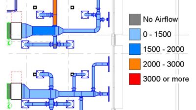
BIM also gives the constructors confidence to prefabricate materials, which saves many hours of field labor. Valves/valve tags can be linked from the flow diagrams to the floor plan to help facility engineers troubleshoot the general cause and effect of valve-position changes. Likewise, power outages can be viewed on the electrical one-line diagrams to determine the cascade effect of a circuit breaker or fuse opening for quick troubleshooting, all through the power of an integrated BIM. (The level of BIM needs to be negotiated at the project’s front end for intent and to determine which parts are assigned, so fees can be calculated without asking for additional services later.)
By fully understanding BIM, identifying how it will be used on a project, and adding more modeling tools to maximize utility, the design and construction team can optimize the many benefits BIM provides.
This powerful tool enables design development to occur more smoothly, even in real time, with team members able to collaborate from various locations. There are ongoing challenges, such as additional time required to enhance the model’s level of detail to fit owner needs and to update the model or manage updates. The benefits, however, include increased productivity and efficiency, reduced general condition costs (by not duplicating office materials at a project site), and continuous updates on cost control and feedback for the project team. Change orders can be minimized, clashes can be detected and avoided, budget control is maintained, and time to market reduced-all good news for the client.