In fashion with the nationwide goal of getting a better handle on health-care costs, one of the country's largest health-care insurance companies, Pittsburgh-based Highmark, decided it would do all it could to achieve economies of scale in developing its new data center. The process began with a decision to remain on the site of an existing facility near Harrisburg, Pa.
In fashion with the nationwide goal of getting a better handle on health-care costs, one of the country’s largest health-care insurance companies, Pittsburgh-based Highmark, decided it would do all it could to achieve economies of scale in developing its new data center.
The process began with a decision to remain on the site of an existing facility near Harrisburg, Pa. Furthermore, the facility would also house approximately 50 IT staff and management. Finally, for public relations purposes, the facility would also need to serve as a showcase, allowing tours and exhibits on how the data center functions—an important aspect considering the company is a major mover and shaker on the information highway. In fact, according to Highmark’s data center director, Mark Wood, the insurer uses a sophisticated B-to-B electronic network that connects more than 100 hospitals and 15,000 health-care practitioners, processes 500,000 claims a day and responds to 33,000 customer inquiries per day.
With such weighty responsibilities, Highmark had lofty expectations for this new facility including:
An infrastructure conforming to the Uptime Institute’s Tier 3 facility standards for reliability (see “Data Center Benchmarks,” p. 50).
An adaptable standard to accommodate evolving IT requirements, both in size and increased power and cooling demand.
A design that conveys a technology message reflecting Highmark’s corporate identity.
A design that allows for future expansion that would eventually include a call center.
Business as usual?
Typical of data center design, the budget was driven by the reliability strategy. Highmark’s priorities included business tolerance of outage, power, water, telephone connectivity and the ability of the selected site to provide redundant sources from the outset—all balanced against the project’s capital expense.
Consistent with Uptime Institute standards, the infrastructure needed to be expandable without compromising reliability or ongoing operations. Design for up to 70 watts per sq. ft. was required for a period of 10 years, even though at day one the load would be significantly less. In other words, a solution was required that would minimize initial construction costs, yet allow phased increases to M/E capacities.
As noted, one of the key differences of this facility, compared to other data centers, is that the building would be occupied by humans. Typically, the primary architectural consideration in such work is the environmental enclosure and security of the mission-critical infrastructure. Adding IT and call center personnel, however, meant a whole other set of unique requirements.
Recognizing that shell space would be most efficiently constructed on day one and fit up over time, operational considerations of all scales entered into the process. These ranged from color-coded piping to providing a windowed tour aisle through infrastructure space to door placement and heights that would accommodate equipment changes.
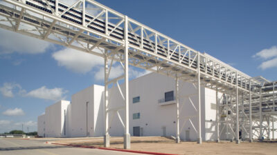
But beyond these standards, Highmark had another goal: sustainability. To maximize green benefits, principles of life-cycle costing, resource management and operational protocol were considered from the outset and developed integrally with facility design. At the same time, the designers were challenged to consider ways that sustainability could be used to enhance the operations and reliability of the facility. The environment—in this case, an 11-acre site upon which the 87,000-sq.-ft. facility was to be built—also threw a unique challenge at the team: It was situated on a sloping hill.
But truly capping it all was the schedule. Timing was critical. Because Highmark set a schedule for IT migration by the end of 2005, the project had to be under construction by June 2004.
Siting situation
Getting down to work on a triangular lot with grades that dropped steadily about 80 ft. across the width didn’t leave a lot of options for a building type that traditionally requires a large, square flat site. But when security stand-offs, expansion and storm-water management were factored in, the slope itself proved to be an advantage, as it offered the opportunity for grade-level access at both levels. This served to simplify emergency egress and maintenance access; accommodate direct distribution into the data center to minimize horizontal piping and conduit runs; and create the less industrial appearance that was desired for this corporate facility. Retaining walls were added, functioning as foundations, grade walls and service accessways.
From a site perspective, the various grades allow visitors and employees to enter the upper-level building lobby from the adjacent parking area. Flanking the lobby, office space looks out over the entry drive, capitalizing on views to the outside and on daylight coming into the management areas, as well as providing a corporate identity to the building. Data center support is right around the corner from the office areas, again, capitalizing on grade and natural light and providing direct access to the data center from equipment burn-in rooms and for vendor support.
At the same time, site selection had a major impact on the M/E/P specs. Because of limited utility service, there was a need for on-site generation, as well as make-up water provided by on-site well water. Electrical service is provided by a 69-kilovolt (kV) feed originating from the sole local substation. On-site power is necessary because the data center is at the end of the local utility’s power transmission system, making electrical service statistically prone to interruption.
Back-up power is provided by a 2N generation plant with parallel systems and 2N power-redundant UPS systems. Installed are a pair of 2-Mw generators. Ultimately, four 2-Mw gensets will be built out. The initial UPS solution features two 750-kVa systems, but like the generators, will ultimately grow to two N+1 with a total of five 750-kVa systems. The facility is a prime-power operation, with redundant 15-kV service entering from the outside.
Despite such high levels of reliability, the M/E/P design solution also balances owner requirements for economy. For example, cooling towers selected for the project are forced-draft centrifugal types. This investment better accommodates year-round operations. And even though they are larger and draw more power, their energy use is offset by enhanced reliability. On the fire protection side, engineers worked with the owner to consider the full array of smoke-detection and fire-suppression systems. As a result, the facility utilizes a smoke-sampling system, operating in parallel with a dry-pipe preaction sprinkler system. More expensive gaseous fire-suppression systems were carried as a price alternative, and even though storage silos on the data floor are equipped with individual gaseous fire-suppression systems, incorporating this throughout the data environment is considered a future capital improvement.
As far as the building program itself, the configuration responded to site requirements, but also to functional needs. For example, data center space was stacked above the M/E infrastructure, creating efficient vertical distribution of power and chilled water, and avoiding horizontal piping in the data center floor plenum. Specifically, pipe loops are located below the floor in dedicated first-level pipe galleries. This limits the amount of water traveling through the data center and reduces the incidence of pipe crossings. In addition, the actual loop is designed to be able to isolate leakage and still provide chilled water from two directions.
A 2N strategy
The engineering systems were designed to meet the Uptime Institute’s Tier 4 requirements. However, recognizing that systemic fault tolerance equals increased first cost, RTKL was asked to execute a Tier 3 solution. In fact, both electrical and mechanical systems incorporate a 2N strategy in which reliability is provided by the dual paths that connect each piece of equipment to intermediate distribution from incoming service. At the same time, Highmark maintains the ability to escalate to a Tier 4 solution where improvements to the physical and engineering infrastructure can be plugged in without downtime. For example, redundant UPS battery, switchgear pads and conduit are in place for future installation. The requirement for physical separation of switchgear is accommodated in room proportions to allow for eventual construction of partitions.
The engineering design incorporated a variety of other innovations. For instance, the project required electrical systems that provided minimal capacity from day one: 30 watts per sq. ft., nominal. That said, the design would also have to account for an increased load capacity over time—up to 70 watts per sq. ft., nominal, without downtime. The engineering solution included multiple bypasses that allowed equipment isolation, which required refinement of industry standard specifications to incorporate bypass switching within the switchgear. Specifically, it’s a “5-breaker throw-over” system that requires fewer cross connects and is easier to maintain. Regarding the bypasses, the solution incorporates multiple static switches for AB redundancy, and major systems such as UPS and switchgear have concurrent redundancy.
The approach addressed Highmark’s evolving power-density requirements and accommodates the transition from legacy IT equipment to new IT equipment over a period of years.
Eye on sustainability
Being that sustainability was a key project goal, the design capitalizes on opportunities to enhance workplace productivity through environmental design, increase the reliability of mission-critical building systems and reduce operating costs resulting from to the increased energy efficiency of the facility.
Similarly, the facility was designed to earn a U.S. Green Building Council Leadership in Energy & Environmental Design silver rating. This forced the project to balance the incremental cost of sustainable design elements against one another in order to develop a program that fell within the overall budget. Sustainable strategies include recycled and renewable materials and enhanced daylighting and environmental controls. Site design features extensive storm-water management as well as groundwater replenishment strategies.
Sustainability objectives were also integral to the M/E engineering design solutions. By its nature, a data center requires precise calibration and efficient operation of its infrastructure, which can only be confirmed through building commissioning. Consequently, it is no coincidence that LEED certification requires this process to confirm efficient energy consumption. Thus, the project introduces enhanced environmental controls and promotes energy efficiency throughout. Individual work areas are equipped with temperature controls, lighting controls and CO 2 monitors, all tied back to the central controls. The project also has lower ozone depletion potential by eliminating CFCs through the use of R134a refrigerant in the chillers.
Up to half of the project’s requirement for 100,000 gallons of backup water is provided naturally by capturing rainwater and keeping it in a storage cistern. This innovative approach incorporates a water-storage system to reduce demand on the local aquifer and municipal water supply. When treated, this water is introduced into the building’s cooling system and is even leveraged to provide gray water for toilets.
In the near future, the project will also apply for innovation credits that recognize the increased M/E system efficiencies associated with utilizing a high delta-T strategy for cooling the data center. This design approach reduces electrical demand by upwards of 10% compared with conventional cooling. In addition, it provides a more reliable, less outage-prone environment for IT equipment.
But Data Center Director Mark Woods perhaps says it best: “Our members will have peace of mind knowing that their personal health information is being processed, protected and safeguarded.” And with the new facility, “Highmark is positioned to take on new business opportunities now and into the future.”
Click here
A Marketing Tool Too
An interesting aspect of Highmark’s new data center near Harrisburg, Pa. is the insurer’s desire to showcase the uniqueness of the operation to a wide variety of visitors. This necessitated a tour experience based upon the purpose of the visit. The M/E team’s design response was to provide a series of tour circuits through the facility offering increasing levels of information and insight into the operation of the building.
The tour begins in the lobby where sound and display systems welcome visitors. Guests are then escorted into an orientation area where flat-screen presentations describe the facility’s purpose. They continue into the tour aisle, a corridor separating the data center from the command center (pictured on p. 54), and experience a panoramic view of Highmark’s data center operations. The aisle slopes gradually upward on open-floor grating connecting visitors to the sound and temperature of the data environment. Continuous glazing maintains a secure separation, while offering a 180° vista across the data space. The opportunity to ask questions is provided via wireless headsets. As visitors survey the data center, operational activity continues behind them without interruption. Windows in the command center provide a view through the tour aisle into the data center.
The tiered command center will accommodate up to 16 flat-screen workstations supported by rear-screen projection at the head of the room. To the rear, the elevated command center briefing room will overlook the space and provide video teleconferencing capability in support of command center activities. The tour aisle concludes outside the entrance to the briefing room on an elevated platform with a gathering space overlooking an area of transparent flooring, which reveals the electrical, mechanical and communication “guts” of the building.
Beyond this point, tour groups are either escorted back to the lobby, or depending on the purpose of the visit, can continue downstairs to the infrastructure level where a windowed central corridor provides direct views of the gear that keeps the facility running.
Data Center Benchmarks
The Uptime Institute (
Tier 1 facilities offer a single path for power and cooling distribution, no redundant components, 99.671% availability with an annual anticipated IT downtime of 28.8 hours (all systems are “N”). Such a facility has computer power distribution and cooling, but it may or may not have a raised floor, a UPS or a generator. If it has the latter, the system is single-module systems and has many single points of failure.
Tier 2 facilities offer a single path for power and cooling distribution, redundant components, 99.671% availability and an annual anticipated IT down time of 22 hours (N+1). Such a facility will have a raised floor, UPS and generators, but its capacity design is “Need plus One.” Power and cooling have a single-threaded production and distribution path. Maintenance of M/E systems requires an outage.
Tier 3 facilities feature multiple power and cooling production and distribution paths, but only one path is active at a time; redundant components are concurrently maintainable; and there’s a 99.982% availability with annual anticipated IT downtime of 1.6 hours ( all systems are N+1). This is similar to Tier 2, but with the addition of a second path for power and cooling. For more critical power distribution, this can be translated into dual-corded computer equipment connected to the output of a single UPS system or a single UPS and raw electric utility. Mechanical systems require two independent cooling means. Maintenance of any M/E component can be accomplished on a planned basis without a critical outage.
Tier 4 facilities feature multiple active power and cooling production and distribution paths; redundant components; fault tolerance; and 99.995% availability with annual anticipated IT downtime of 0.4 hours (all systems are “System + System” or 2 [N+1]). The difference between Tier 3 systems is that the second path is active at all times allowing at least one worst-case unplanned failure while maintaining uninterrupted load operation.
Tier 4 site infrastructures are the most compatible with high availability IT concepts that employ CPU clustering, RAID DASD and redundant communications.
That said, even a fault-tolerant and concurrently maintainable Tier 4 site will not satisfy an IT requirement of “five nines” uptime. The best a Tier 4 site can deliver is 99.995% and this assumes that an outage occurs only as the result of a fire alarm or EPO, and that such an event occurs no more than once every five years. Only the top 10% of Tier 4 sites will achieve this level of performance.