Engineers should understand NFPA 99 — along with other guidelines and codes — when designing health care facilities

Learning Objectives
- Understand how NFPA 99 works with other codes, standards and guidelines in hospitals.
- Provide an understanding of guidelines for medical gas systems.
- Review telecommunication and information technology codes in health care facilities.
NFPA 99: Health Care Facilities Code covers various systems relative to health care facility design. NFPA 99 applies to all health care facilities other than home care or veterinary care. Requirements are applicable to new construction and equipment.
Existing building system upgrades are needed only if new construction negatively impacts the systems’ overall performance or if the existing systems — particularly source equipment — do not meet the current NFPA 99 guidelines to support and meet the requirements to support the new use or program. Any design criteria implemented in a facility must ultimately meet the approval of the authority having jurisdiction.
The documents included in NFPA’s codes, guidelines and standards are intended to work together as a total package. The acceptance of specific NFPA guidelines by the particular AHJ and as required by the Facility Guidelines Institute and local building codes, form the basic design criteria for the engineered hospital systems and their use.
Clients may choose to provide systems or criteria that are above and beyond these basic requirements for their specific facility or campus. It is also important to note that NFPA may update or supersede certain items by issuing tentative interim amendments or errata at any time. These modifications and information are evaluated as they apply to the client’s needs and requirements.
Design engineers and architects involved in health care engineering design are constantly referring to these guidelines as they prepare their designs and documentation. In addition to these guidelines, the design is often impacted by the acceptance from the local department of health, Health and Human Services, the Centers for Medicare & Medicaid Services, the Food & Drug Administration and the National Institutes of Health. Additional agencies that will have input into certain aspects of the requirements could include the Centers for Disease Control and Prevention, Occupational Safety and Health Administration, ASHRAE and American Society for Health Care Engineering.
The use of the included terms, acronyms and common phrases that appear in the NFPA guidelines should be integral to the designer’s vocabulary and represented in the documentation. Providing uniformity between these references and the design documentation is extremely important to ensure proper understanding of the design intent.
The risk categories identified and described in NFPA 99 Chapter 4: Fundamentals relate to the classification of areas and related systems for the application of specific guidelines. There are four categories of risk defined. Generally, the categories are established based on the risk of life, with Category 1 being the most stringent where failure of systems is likely to cause major injury or death to patients, staff or visitors. The other end of the spectrum, at Category 4, the failure of equipment and systems would not cause any impact to patient care.
General considerations
The requirements and standards identified in the NFPA 99 and the FGI guidelines provide the minimal requirements for any health care facility design and construction. Based on the adoption of these standards and the understanding of the systems to be installed and the required basis of design, it is with this understanding that we use Chapters 4 through 11 of NFPA 99.
With the input of the client, the risk category can be established. Specific design criteria can be verified and then reinforced or form the basis with various users of the facilities, which may have additional requirements that will need to be integrated into the overall building systems that will ultimately create the basis of design for the facility.
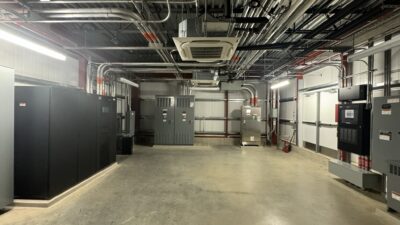
Medical gas systems
The design and installation of medical gas and medical vacuum systems relate directly to the client’s determination of compliance with regulatory authorities and the category of use. The determination of these categories relative to the area requirements for anesthetizing, critical care and general care systems or ambulatory services are based on the user’s needs, program and the requirements of the specific layout.
All medical gas systems are required to be constructed of piping that is a minimum of type L copper tubing, washed and capped for oxygen use, with brazed joints. During the brazing process, the piping is continuously being purged with hospital-grade nitrogen. The use of three-piece valves is required so that the valves are not damaged while brazing at a temperature of approximately 1,000°F.
When evaluating the source equipment requirements, the preferred type and sizing of source equipment, there are many criteria to consider. At this time, there are very few applications for water-sealed pumps. Water-sealed pumps could still be considered for a “dedicated” waste anesthesia gas disposal system if the need arises.
There are some areas of the country and there are some clients who prefer water-sealed pumps, based on the related water use and cost. There are many other “dry” types or oil-sealed equipment. From many years of using various systems, the dry vacuum, oil-less rotary vane, claw and rotary screw and oil-less reciprocating or scroll compressors are the most common selection for health care applications for pump operation.
The additional piped nonflammable, medical gases such as oxygen and other required gases including nitrous oxide, carbon dioxide or high-pressure nitrogen are commonly stored as high-pressure in manifolded cylinders or cryogenic, low-temperature liquid bulk or mini-bulk systems. These systems include either cryogenic backup or gaseous backup, but all the medical gas systems require redundancy.
The need for redundancy of systems is identified in NFPA 99. Redundancy can take the form of multiple pumps, secondary gas system with automatic switchover or multiple skids of equipment at various locations throughout a facility. This equipment arrangement can take various forms, with the requirement that the system can support the required flow at the required pressure or level of vacuum if one portion of the system fails to operate properly. The manifolded gas systems would require a duplicate second bank of cylinders with automatic switchover. All systems shall be connected to a form of emergency power.
Some items to consider when looking at the placement and sizing of the required equipment:
- In addition to validating the engineers sizing of source equipment with the supplying vendor, the calculated line size that serves the facility should be approximately the same size as the source outlet piping serving that portion of the facility.
- The use of skid-mounted, multiple, smaller capacity pumps and compressors allow for redundancy by supplying an additional smaller unit. This concept allows for varied flow, with the units coming online as they are required by the usage, but with the redundant unit always at rest.
- The installation of vacuum exhaust and medical air intake piping will need to be sized in accordance with the vacuum pump or medical air compressor suppling manufacturer recommendations. Normally, based on required length, offsets need to occur and a need to have very little dynamic friction loss; the line can become very large very quickly. The piping, unless approved to be of a different material, should be the same piping system types as the distribution to the health care facility.
The piped medical gases, other than medical air, are commonly provided through source storage of gas or liquid that is vaporized through changes in temperature.
Figure 4: This is an example of a typical zone valve box for anesthetizing location use. Alarm sensors are upstream of the zone valve box, based on the anesthesia equipment in the operating room. Courtesy: CannonDesign[/caption]
Care should be taken to work with the independent medical gas certifier to ensure that the work agrees with the interpretation of the inspector, or if the inspector has not interpreted the system properly. The misunderstanding or unclear documentation can lead to confusion and additional time and costs to the owner. To avoid this, a clear presentation shall be made to the owner in the presence of the independent testing agency before installation of the systems.
Medical air systems
The oil-less medical air compressor systems, as specified and applied, should be provided as a complete skid system with “makeup” to a storage receiver, allowing for cycling of the compressors. Depending on the supplier and the capacity required for the system, the dryers and or final treatment could be located on separate skids and require induvial electric connections.
The sequence is normally set up as primary and secondary and the multiple units operate as is a lead-lag system with alternating lead compressors to allow for even usage across all of the compressor units. The other components of the systems include intake filtration, dryers (refrigerated or desiccant), filters, carbon monoxide monitor, dewpoint monitor and regulators. All components shall be duplexed and valved with a bypass for maintenance and isolation.
The medical air usage requirements, both pressure and flow, require that there is a sufficient volume of compressed air for the worst-case situations. The source equipment is selected with a limited amount of diversity as established standards. The delivery pressure to the building is normally in the range of 55 psig. The pressure generated at the compressors must account for loss occurring at the dryers and filters up to the main pressure regulators, in addition to the dynamic loss through the piping system out to the point of use. In the case of supplying medical compressed air to ventilators, normally mixed with oxygen, it usually is an instantaneous loading that can be accomplished through proper pipe sizing and accommodations within the source system, once the quantity of units and the “inflating” volume of the specific ventilators are known.
The “source” pressure regulating station would be the last component of the equipment, upstream of the monitoring and alarm functions. The compressed air generated up to the regulators can be as high as 100 psig. The piping pressure loss can be selected by the designer, based on the requirements of line pressure, capabilities of the compressors and the required point of use pressure and volume requirement. There are many things to be considered with respect to supplying compressed air to a building occupant.
Common piping dynamic losses through the piped distribution can be designed for 4 to 5 psi for 55 psi systems. The process is to estimate the total developed length from the regulator to point of use farthest away with the required residual pressure at the required flow.
All medical air systems, piping, valves and components must be in accordance with the most recent edition of NFPA 99. There are different levels of medical air piping systems that apply to specific facilities, such as general hospitals, ambulatory facilities, dental, etc. For our designs, the ambulatory facility will be addressed as a hospital condition unless directed otherwise by the owner.
Medical vacuum systems
Medical vacuum is normally considered a “dry” system and the system includes a “trap” or bottle at the point of use, using the adjacent “slide” to hold the trap bottle.
The delivery is 11 to 15 inches mercury for patient rooms and general use, at times it is required to have an elevated vacuum level at surgery areas that elevated vacuum could be in the vicinity of 15 inches mercury. If the user has a need for a “higher” level of vacuum, this would necessitate the installation of a dedicated pump system and piped system. The flow at the inlet is based on the use, normally it varies from 1.0 standard cubic feet per minute based on the system conditions in a patient room and a value to 3½ to 4.0 SCFM per outlet for operating rooms or special procedures. No diversity should be applied to the surgery areas or similar predetermined areas.
Other vacuum systems such as waste anesthetizing gas disposal through a dedicated medical vacuum system or connected into the hospital’s medical vacuum, a distance of 5 feet from the room inlet fitting or, more appropriately, at a location immediately downstream of the zone valve box serves the anesthetizing area.
All source equipment systems shall have multiple pumps. All system components, alarms and monitoring shall be in accordance with the latest adopted NFPA guidelines. The system component and pump sizing need to be in accordance with the manufacturer’s recommendations. Once the engineer has established the intended capacity and sizing, it shall be reviewed to validate the sizing and ensuring the manufacturer’s warranty.
The system can be either a rotary vane, claw or a liquid ring system. If the system is intended to handle WAGD, do not use a rotary vane system; the function of the rotary vanes is not compatible. Any use of water seal shall be reviewed to include water reclaim or recirculation to limit the disposal of once through seal water. A customary approach is to provide a dry rotary vane pump set and galvanized tank/receiver, when WAGD is not being introduced to the piping system. System pressure drop across the piping network shall be a maximum of 5 inches mercury at the calculated demand flow.
To use various measurements of air and the conversion at levels of vacuum, specifically actual cubic feet per minute minus SCFM.
Waste anesthesia gas disposal
The installation of the waste anesthesia gas disposal system is required to “collect” the waste anesthesia from the locations using anesthesia gas through the anesthesia machine. The release of the waste anesthesia gases to the room can cause harm inadvertently to the patient and the attending surgeons, nurses and staff within the room.
The collection of WAGD can occur either by a dedicated system or as a connection into the medical vacuum system. The piping connection to the medical vacuum system is allowed a distance of 5 feet from the room inlet fitting or more appropriately at a location immediately downstream of the zone valve box serving the anesthetizing area.
Dental vacuum system
The dental vacuum system is a low vacuum level system, more similar to a fan-type unit, developing vacuum levels of only approximately 6 inches mercury. The minimum system demand, unless noted by the user, is based on approximately 198 liters per minute (7 SCFM) per dental chair and at an operating pressure of 21 to 27 kilopascals (6 to 8 inches mercury). A minimum of vacuum of 21 kPa (6 inches mercury) shall be maintained at the most distant outlet. The dental vacuum system is a partially wet system that will carry some particles through the system. The piping system shall include an amalgam separator on the piping system before the vacuum source blower(s) system to keep the debris from entering the vacuum source equipment. The separator must include a sight glass and level alarm, for visual observations of liquid and material.
Various users will require multiple pump arrangements and multiple separators to allow for periodic shutdown and required maintenance. The common piping system is polyvinyl chloride or other plastic piping system. Be aware not to run this system through a plenum without proper precautions and fire rated applications.
Alarm systems
Medical master and area gas and vacuum alarm systems are required in accordance with NFPA 99, all systems are required to be alarmed and certified by an independent inspector, normally hired by the hospital or facility.
Information technology, communication systems
The infrastructure design is heavily impacted by the requirements in NFPA 99, FGI and other governing codes and has increased the necessity for design engineers focused on structured cabling and low-voltage communication systems to become involved in hospital design at the onset of a project to ensure proper space planning for telecommunications services and equipment. When reviewing the requirements of FGI and NFPA 99, there are discrepancies that lead to some extensive requirements. It is important to understand the challenges and inform the AHJ of any items that increase space requirements without necessity to reduce overall costs.
NFPA 99 Chapter 7 applies to all new health care facilities and new construction. Existing systems that have portions renovated, shall be upgraded to meet any updated code. If upgrades to the system negatively impact the overall system, it should be upgraded to eliminate that impact. An existing system that does not comply may continue to remain in use if the AHJ determines it is not a distinct hazard to life.
There are three main subject areas compiled within Chapter 7 that are descriptive and several more that are reserved for future development. The “premises distribution system” section includes fiber/copper cabling systems and telecommunications space and pathways. It provides references to Telecommunications Industry Association 568-B: Commercial Building Telecommunications Cabling Standard and TIA 606-B: Administration Standard for Telecommunications Infrastructure, which are industry standards for commercial building telecommunications cabling and administration of cabling infrastructure. It also partitions each section by category to ensure that each of the systems of NFPA 99 Chapter 7 meet the mandated risk assessment.
Category 1 systems require two physically separated service entrance pathways into a facility. This requirement increases the reliability of the service into the building. Furthermore, the term physically separated is defined as 20 feet between entrances, which reduces the risk of an outage by any service/maintenance on the grounds being disrupted by any below-grade level construction.
If the facility being designed has a remotely located primary data center, two dedicated entrance facilities are mandated again requiring two service entrance pathways. It is common for hospitals to use cloud computing and have resources located remote to the building. Service entrance redundancy is paramount in hospital design and should be considered for the entire designed route as well as using multiple service providers to ensure uptime. With many health care systems obtaining remote facilities or facilities trying to centralize data infrastructure, routing diversity is a positive redundant design approach.
The entrance facilities shall be located as close as practical to the building entrance point and not be subject to flooding. The entrance facilities shall be dedicated to low-voltage communications systems and not contain any mechanical or electrical equipment or fixtures not directly related to the operation of the entrance facilities. This requirement includes sprinkler piping that does not branch off and create an endpoint in the telecommunication space.
Each health care facility is required to have a telecommunications equipment room to house application servers, network equipment and storage devices. Based on size and location, it can be collocated with an entrance facility. However, it must be located away from exterior curtain walls in some geographic areas which may be prone to hurricanes or tornadoes. Facilities using a remote data center or cloud solutions tend to have nominal servers on-site with the exception building automation system or security solution servers.
Telecommunications rooms are also required to support communications services throughout the building. A minimum of one TR is required per floor and shall serve a maximum of 20,000 square feet of usable space on a single floor. In addition, communications cabling must not exceed 295 feet in pathway length. These items will allow Ethernet cabling installations and the functionality of power over Ethernet services to support low-voltage systems within a hospital.
There is a push for gigabit passive optical network installations in health care facilities, which do not have the length limitations of Ethernet cabling. Using these networks does not eliminate the need for telecommunication spaces which also provide power via the Ethernet cabling system for many systems. PoE solutions are a great way of providing uninterruptible power to “internet of things” devices without additional coordination of uninterruptible power supply or emergency power outlets.
Like the telecommunications equipment room and entrance facilities, telecommunications rooms have environmental and security requirements. These spaces shall have a positive pressure differential, controlled temperature and humidity to meet the installed equipment specifications. These spaces shall have restricted and controlled access and not be located in a sterile area. The spaces shall also be designed to avoid vibration and damage from water. Stacking telecommunication spaces in a building is highly recommended to simplify riser installation, but not required.
NFPA 99 does not provide or recommend sizes for telecommunications spaces. Telecommunications equipment rooms, entrance facilities and telecommunications room spaces are only required to provide working clearances about racks and cabinets to meet NFPA 70: National Electrical Code Chapter 110.26 (A). This requirement calls for 3 feet of clearance in front of 120-volt equipment for maintenance.
Although FGI requires more space and more confusion, the NFPA 72 reference is a much more accurate way of depicting the actual working space requirements in a telecommunications room because working space is only required at the front and rear of racks/cabinets or in front of panels. This allows engineers to design and layout the room as it is intended.
Connectivity of services is also called out in this section. Redundant pathways are required between the entrance facilities and telecommunications rooms for Category 1 systems. This requirement is eliminated in Category 2 systems, which have a lower risk assessment. Category 3 systems additionally eliminate the dual service entrances for the building.
Nurse call stations
NFPA 99 addresses nurse call within other communications systems. The nurse call system provides vital communications between patients and caregivers and between caregivers in a health care facility. All nurse call systems shall be UL 1069: Standard for Hospital Signaling and Nurse Call Equipment listed and consist of an audiovisual type (two-way voice communications) system or tone-visual type system listed for the purpose.
NFPA 99 refers to FGI for the placement of nurse call devices throughout the health care space and supplements that information with some listed requirements. For patient area call stations, each patient bed location shall have a call station and that call station can serve up to two patient beds if it is an audiovisual system. Bath stations are required at an inpatient toilet, bath, shower and shall be accessible to a patient lying on the floor by use of a pull cord.
Staff emergency call and code call stations are permitted in areas that do not require two-way voice communications because the patient is under constant visual surveillance in such areas as pre-operative and recovery. Dementia units have special requirements such as tamper-resistant features, removal or covering of devices and limited cord lengths of 6 inches.
Nurse call systems are not required in psychiatric units, except for seclusion/ante spaces where a staff emergency station is required.
Finally, the resultant activation of a nurse call device is listed in notifications signals. Staff emergency calls and code calls shall be visibly and audibly identifiable from other nurse call signals increasing the recognition of the calls. These parameters require initiation of the associated dome light in the corridor, zone dome light at intersections leading to the dome light when not visible from the nurses’ station, nurse master station originating station and each audio calling station indicating voice circuit operation.
The single differentiator for Category 2 or higher systems is that code calls and medical device alarms are not required for annunciation in these facilities.
Clinical information systems are a new addition to NFPA 99-2018. It identifies the clinical network requirements for a dedicated network infrastructure for use by clinicians and patients and all manufacturer’s equipment that is connected to the network. It provides for a network that is now allowed to transport medical systems information on an owner-provided infrastructure resolving the solution of alarms on nurse call systems that are UL 1069 listed to operate using an Ethernet network. In previous editions, the nurse call system required a fixed, proprietary connection to route emergency notifications to areas between telecommunication rooms that were connected by backbone fiber cabling. That is no longer required.
The clinical IT network shall have redundant, operable supervised segments for the backbone and they shall not share traffic. Individual addressable devices shall be allowed to be connected as a single endpoint. If multiple devices are connected on the same segment, a supervisory loop shall be incorporated. Each of these items improves the reliability of the system and increases patient safety.
Wireless phone and paging integration are also new to the 2018 edition. It identifies the use of communications handsets (wireless phones) for clinical operations such that alarms and alerts are managed similarly to the other clinical IT components.
It is the health care facility’s responsibility to maintain and be accountable for the clinical IT network and all of its components. All information and systems shall be documented and events shall be evaluated, with risks reassessed to verify all processes to ensure corrective precautions are taking place. The health care facility clinical IT risk manager shall be appointed to verify this work.