When designing standby power systems for facilities such as data centers, hospitals, pumping stations, generation or processing plants, engineers should make informed decisions regarding proper generator size and operation methods to protect critical loads.

Learning objectives
- Learn which factors to consider when selecting generators for specific applications.
- Know the major criteria necessary to determine proper generator size.
- Understand that electrical power system software can be used to perform generator sizing and system evaluation.
Engine-driven generators are the optimal candidate to provide emergency and standby power in case of normal utility failure. Due to the critical role of this system, electrical engineers must ensure that generators are appropriate for that specific application, can supply required power to the loads under designed conditions and evaluate the impact if it is paralleled with a utility.
To choose the appropriate generator for the application, engineers should take several substantial factors into consideration, including technical codes and standards, potential site constraints and prime mover selection.
Codes and standards
Engineers should review state, local building codes and applicable standards in detail with reference to the facilities and equipment the generator will be powering. This review process may reveal requirements for standby or emergency power. Generator designs that are not required by building code are not immune to performance and installation requirements. The following major technical codes and standards are applicable to a variety of systems and should be reviewed (where applicable) and considered when choosing a generator:
- International Building Code.
- NFPA 70: National Electrical Code Articles 445, 700, 701, 702 and 705.
- NFPA 110: Standard for Emergency and Standby Power Systems.
- NFPA 101: Life Safety Code.
- IEEE 142: Recommended Practice for Grounding of Industrial and Commercial Power Systems.
- IEEE 493: Recommended Practice for the Design of Reliable Industrial and Commercial Power Systems.
- IEEE 519: Recommended Practice and Requirements for Harmonic Control in Electric Power Systems.
- IEEE 602: Recommended Practice for Electric Systems in Health Care Facilities.
- IEEE 666: Design Guide for Electric Power Service Systems for Generating Stations.
- S. Environmental Protection Agency.
Consider site constraints
Environmental impact, local ordinances, fuel facilities, site infrastructure and maintenance preferences should be considered when evaluating potential locations for the generators, including local and federal code limitations for operating hours and emissions.
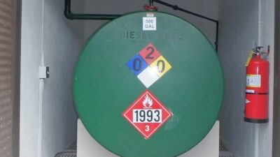
For example, generator noise may become a nuisance to nearby locations. Exhaust stacks are often ill-received by neighbors and communities. Fuel storage facilities require access for truck delivery, therefore, attention to spill prevention and containment is needed. Preferences may dictate an indoor installation to allow maintenance in a climate-controlled environment. As an emergency power source, generators should be placed in a protected or elevated portion of the facility, so it can endure events such as flooding.
The EPA provides regulations for the control of emissions for diesel generator. The EPA uses tier ratings to enforce the regulations on these emissions based on the year the generator was built or originally purchased, the application of the generator and the size of the generator. The higher the tier, the more stringent the requirements for emissions regulations.
Relating to emergency standby diesel generators, they are currently exempt from the latest Tier 4 regulations. These are required to either be Tier 2 or 3, depending on the size of the diesel generator. Depending on the application, diesel generators may be required to meet certain EPA regulations for exhaust emissions control.
Prime movers
When selecting prime movers, three options are typically considered: diesel engines, gas engines or gas turbines. Diesel engine generators are commonly considered for standby and emergency applications where an extremely reliable source of generator power is needed when the typical power source is not available. Diesel engine generators also can be specified as bi-fuel to start on diesel fuel and operate on natural gas. These generators are strong candidates for critical, emergency and standby power applications. Diesel fuel can be stored in large quantities on-site, allowing the generator to operate independently.
Diesel engines are very effective for picking up and dropping motor loads. However, they present maintenance concerns, such as wet stacking when underloaded, and require regular interval testing, which will help prevent moisture buildup. Additional mechanical and civil engineering design is required for the fuel storage and emissions requirements. In addition, some owners prefer certain types of generators, such as natural gas, so they can continue to use them during prolonged power outages and not be concerned with the delivery of fuels (diesel, etc.). Also, cost considerations will vary based on the type of generator and operation, however, these options and evaluations are not discussed in this article.
Figure 4: Load flow analysis with a 1,750-kilowatt generator operating in island mode. Courtesy: CDM Smith[/caption]
Sizing generator systems
It is essential that engine-driven generators are sized correctly for various loading scenarios and to supply the required power to perform the specific designed function (e.g., pump, fan). If this power source is undersized, it may create issues within electrical distribution systems, including loss of loads.
In addition, during load steps (i.e., load sequencing), such as a motor starting across the line can cause high inrush currents and consequently, substantial voltage dips. The generator must be sized appropriately to allow such significant voltage and frequency dips when these loads are started or suddenly rejected. Gradually adding loads to the generator by multiple load steps may help reduce these significant voltage and frequency dips. The generator would observe several smaller dips in voltage and frequency rather than one large dip.
Figure 6: Voltage response at generator bus during starting sequence as shown in Table 1. Courtesy: CDM Smith[/caption]
Emergency standby generator sizing
The following case study provides an example of major parameters, considerations and the necessary steps to determine whether a standby/backup generator at a water pumping station facility is sized properly.
The existing generator at this facility is 1.25 megawatts, 4.16 kilovolts, 1800 rpm, with 0.8 power factor. A simplified electrical distribution system ETAP model with loads fed from the standby source is shown in Figure 3.
The most important factors used to determine the proper generator size when operating in island mode are:
- Determine the total required electrical power loads by adjusting load factors, including a reserve for future expansion. Generally, there are two different loading categories to consider when sizing the generator. These categories are based on project specifications, requirements, cost, safety margin and load types, such as critical, noncritical, etc. These categories — load steps with 100% load factor and load steps with different load factors based on functional loading requirement — are shown in Tables 1 and 2. The major difference between these two is the load factor based on mechanical/system loading requirements. Based on the data in Table 1, the minimum kilowatt generator size should be equal to or greater than 1,688 kilowatt, with 100% load factor. The minimum generator size should be at least 1,478 kilowatts with a different load factor based on functional loading requirement, as seen in Table 2. In this case, the generator size is selected based on 100% load factor and available size in the market, 1,750 kilowatts with 0.8 power factor. Design and control of the generator power distribution needs to consider load classification per NFPA 70: National Electrical Code (emergency load, legally required standby load, optional standby load).
Load flow analysis with a 1,750-kilowatt generator operating in island mode is shown in Figure 4. After selecting the proper size, two other factors also should be analyzed.
- Ensure that the load steps during load sequencing are within the generator kVA capabilities and within code requirements for each specific component. The plot for this case, based on tabulated load steps in Table 1 and overall system power factor, is shown in Figure Generator kVA capability, such as cumulative kVA (i.e., starting kVA at the last step) and maximum kVA step during the entire sequencing should be evaluated against published generator data. If the data are not available, it should be evaluated through communication with the generator vendor.
- Evaluate whether voltage and frequency variations are within the generator limits and code requirements during load sequencing and load rejection. Significant voltage or frequency dips can cause the prime mover to stall and the generator set to fail to provide its functions as designed. To reduce the generator size and operation issues, the load should be added in incremental steps. It should be ensured that voltage and frequency variations are within the generator limits during load sequencing and load rejection. Voltage response based on loads tabulated in Table 1 is shown in Figure 6. The motors are assumed with 1-second acceleration time to evaluate the voltage dip during the start.
In addition, load steps are assigned (i.e., starting time in seconds) to not overlap during the sequencing. This is one of the general issues related to voltage dip during load sequencing in industry. As shown in Figure 6, in load step at 7 seconds, voltage will dip below 20% of its rated voltage, which in most cases is not permissible based on motor characteristics. Therefore, additional actions, such as using motor soft starting devices or VFD, should be considered as previously discussed.
Paralleling considerations and impacts
When determining whether generators with utility systems should be paralleled, the capacity, redundancy and compliance should be considered. A paralleled system allows additional generator sets to provide combined power during times of higher loads. It allows generators to use a standby control and permits more convenient maintenance due to consistently available standby power.
Power utility companies are willing to allow customers to produce power in parallel with the grid. However, wading through the bureaucracy of utility regulations and requirements can be a daunting task. A major concern of the power companies is generator fault contribution. On-site generation interconnected with the power utility will supply power to a fault located on the utility network. Utility networks in many areas are often congested and outdated, therefore additional fault contribution becomes a risk that power companies are unwilling to entertain without careful review.
To assess this risk, engineers should carefully analyze the electrical system to determine how much fault current will be injected. This analysis will become extremely valuable when discussing fault mitigation techniques or system upgrades with the power company. The following case study provides an example of this analysis.
Parallel generator operation with utility
This facility’s electrical substation is composed of five 27-kilovolt utility service feeders, five 3 MVA transformers, primary switchgear and 4,160-volt distribution switchgear. The oil-cooled substation transformers are located outdoors and the switchgear is located inside an adjacent building. The primary switchgear is configured with metering and vacuum circuit breakers to protect each 3 MVA transformer.
The 4,160-volt distribution switchgear is fitted with an overhead auxiliary busway and relay protection to allow all five transformers to supply power to the treatment plant in a parallel configuration. The substation includes existing relay protection configured to monitor and protect the utility network from reverse power (32) and directional overcurrent (67). The primary switchgear and distribution switchgear are also provided with kirk-key interlocks to prevent on-site sources of standby power from operating in parallel with utility power.
The proposed facilities include two 1.8-megawatt on-site cogeneration units. The maximum power output from the proposed on-site generators is not anticipated to exceed minimum base load of the facility. Power generated from the on-site synchronous generators is intended to reduce power imported from the utility. Power generated from the on-site synchronous generators would not be intentionally exported or sold to the utility company. A control system architecture is proposed to modulate output of generators based on available fuel. In this case, analysis assumptions include:
- Both gas generators are operating at full load.
- All five utility substation transformers are energized and synchronized.
- Standby generation sources are disconnected via kirk-key interlocking scheme.
- Plant load fault contribution from two 1,000-horsepower blower motors and two 600-horsepower pump motors.
- Analysis is based upon 100% pre-fault voltage.
- Analysis considers utility short-circuit data obtained previously.
- For demonstration purposes, only a three-phase short circuit is discussed here.