Learn about the details of fire pump design and interdisciplinary coordination throughout the design process
Learning Objectives
- Understand code requirements for fire pump systems, including NFPA 20.
- Learn how to size a fire pump and jockey pump.
- Grasp the coordination of fire pump systems with other disciplines.
When fire pumps are required to supply the fire protection system demands for a facility, there are many factors associated with the design and coordination of the system. The basic functional purpose of a fire pump is to boost the available water pressure to the demand requirement at the appropriate flow demand. NFPA 20: Standard for the Installation of Stationary Pumps for Fire Protection is the guiding standard for the selection and installation of pumps for private fire protection.
This article considers the design of a fire pump system for new facilities or existing facilities adding a new fire pump and room. All references to NFPA 20 are to the 2019 edition unless noted otherwise. Note that NFPA 20 is intended to provide a reasonable degree of protection for life and property from fire. Project requirements or industry best practices may warrant additional provisions.
The initial considerations for a fire pump include the room location and access at the given facility. Section 4.14.1.1 of NFPA 20 provides the guidance for indoor fire pumps. The designer should plan to provide a dedicated fire pump room to house the fire pump equipment. The room should be sized to include all equipment while factoring clearance around each component for access and maintenance.
While the standard does not quantify the clearance dimensions, 3 feet should be considered where possible. For better space efficiency, equipment clearances can overlap one another. The room shall be free of storage and penetrations not essential to the operation of the fire pump and related components. Equipment not serving the fire suppression system, such as boilers, should not be located within the same room. While equipment related to domestic water distribution is technically allowed in the fire pump room, best practice is to keep this equipment in separate rooms.
Additional considerations for the room include the means for providing pressure maintenance in the system. NFPA 20 now expressly requires a means of maintaining the system pressure without use of the fire pump itself. While there are options for providing pressure maintenance, a jockey pump typically satisfies this requirement.
Over the years, requirements for access to the fire pump room have evolved. The 2013 edition of NFPA 20 required the fire pump room to be accessible directly to the outside or through an enclosed passageway from an enclosed stairway or exterior exit with a fire resistance rating no less than that of the fire pump room. The 2016 edition was updated to only require that the fire pump room location and access be preplanned with the fire department, which has remained the same in the 2019 edition.
Sizing a fire pump and jockey pump
The first place to start when calculating the fire pump flowrate and boost pressure is with a current flow test report. While timelines vary, most jurisdictions require a flow test report to be current within 12 months. For greenfield facilities, the test and report should be conducted and provided in accordance with NFPA 291: Recommended Practice for Fire Flow Testing and Marking of Hydrants.
If a “low grade” pressure condition is not given, a conservative estimate of the lowest potential supply should be taken at the engineer’s discretion. From there, the big question of “Is a fire pump needed?” can be answered. Without current documentation of the available water supply, a fire pump should be assumed. If it is not, the project could be at risk. Risks include schedule delays and extra costs stemming from additional architectural work, fire pump equipment, power, fire alarm monitoring points, drains, etc. that were not previously included in the project.
For this calculation example, we will consider an automatic wet, class I standpipe system for a high-rise building (see Figure 1). The left side of Figure 1 depicts a dry standpipe system, typical for an open parking garage, supplied from a dry fire department connection so there are no fire pump demands to consider for this portion of the complex. The first stairwell in the tower extends to the roof and a second stairwell terminates on level 27. The third stairwell only connects levels 0 and 1. You will also notice that Level 1 has several sprinkler zones on the right side of Figure 1. These are dedicated to separate retail areas. To determine the appropriate flow rating for the fire pump, there are a few demands to consider.

First, the pressure and flow requirement for the fire hose connections at the highest level of the building will be considered. Per NFPA 14: Standard for the Installation of Standpipe and Hose Systems Section 7.10, the first stair would require 500 gallons per minute and the second stair at level 27 would require an additional 250 gpm for a combined flow requirement of 750 gpm. The pressure requirement for high-rise standpipe systems is typically 100 pounds per square inch, but may vary based on local amendments.
Second, the demand at the top of the lowest stairwell needs to be determined. In this example, the demand would be on level 1 as all three stairwells are accessible on this level. The flow at this level would require an additional 250 gpm at the third stair, for a total demand of 1,000 gpm at 100 psi. Because the pressure requirement is at a flowing condition, it is important to include losses through the fire hose connection in the hydraulic calculation. Table 8.3.1.3 in NFPA 14 shows that a 2.5-inch angle or hose valve has an equivalent pipe length of 31 feet, assuming a C factor of 120 and schedule 40 piping. This component is often overlooked in design calculations.
Third, sprinkler flow demands must be evaluated. Consider a mechanical penthouse on the roof with ordinary hazard group 1 (OH1) criteria: 0.15 gpm/square foot x 1,500 square foot = 225 gpm. Adding 250 gpm for total hose stream totals 475 gpm.
Another aspect of fire pump sizing that may be overlooked is the need to account for the actual flow required for the most demanding sprinkler zone, which is actually larger than the demand flow. To help distinguish these two values, see Figure 2 for an example OH1 hydraulic calculation showing only the flowing sprinklers.
As you can see, the actual flow required (513.95 gpm) for this sprinkler zone is greater than the simple density times area calculation result with added hose stream (475 gpm). This “overdischarge” flow is an inherent consequence of the actual flow condition of sprinkler systems. The pressures and flows from each sprinkler vary based on pipe sizes and proximity to the fire pump. Given 12 flowing sprinklers in a zone that requires 225 gpm, the simple hand calculation yields a flow of only 18.75 gpm from each sprinkler.
That value is a minimum though, and the hydraulic calculations show the real-world scenario that ultimately satisfies the requirement at all flowing sprinklers. Consider this overdischarge value to be the sprinkler demand for the applicable most remote zone.

Finally, a safety factor should be applied. If the authority having jurisdiction and owner do not have specific requirements, 10 psi is recommended as industry standard. This helps mitigate slight decreases in available source pressure to the pump, field modifications and degradation of the pump over the course of its service life.
NFPA 25: Standard for the Inspection, Testing, and Maintenance of Water-Based Fire Protection Systems considers that fire pump flow rates and pressures recorded at 95% or more of the original field test curve or fire pump nameplate are acceptable. Without a safety factor, the system will be at risk of failing its flow tests even if the fire pump itself is still technically passing its tests.
A fire pump should be selected based on a manufacturer’s performance curve. The pump can be verified as sufficient if all calculated demand points as discussed fall below the curve. Note that NFPA 20 allows up to 140% of its rated pressure at a 0 gpm flow condition. This curve allows our fire pump to supply a smaller pressure at a higher flow, subject to variations in the operational characteristics of the chosen pump. Some curves are much flatter than others. Refer to NFPA 20 Figure A.6.2 for guidance and verify the functional characteristics of the selected fire pump versus the demand points.
While it is rare for a high-rise to have greater demands from the sprinkler system than the standpipes, it must be verified. Hypothetically, consider one of the retail zones in the example building as a dry sprinklered loading dock with a density of 0.3 gpm/square foot over an area of 3,500 square feet per the insurance provider’s recommendations. This sprinkler demand flow of 1,050 gpm would be greater than the standpipe demand. For this reason, it is always important to consider requirements from the owner and individual tenants within a building when sizing the fire pump system.
Once the fire pump pressure and flow has been determined, the next step is sizing the jockey pump. A good rule of thumb is to size the jockey pump at 10 psi higher than the fire pump at a flow less than that of a single sprinkler. This pump should be able to make up the allowable leakage rate in 10 minutes. A jockey pump that has too high of a flow will cause a delay in the fire pump starting. It is important to set the start and stop pressures for the fire pump and jockey pump correctly to ensure proper function. The pressure settings should be checked during the initial acceptance test then again regularly during each following inspection. Refer to NFPA 20 Section A.14.2.6 for recommendations on pressure settings.
As a final thought on determining the demand for the fire pump, any foam systems for rooftop helipads need to be considered in determining the fire pump demand.
Coordination items for the fire pump system
The basics of coordination start in the early planning stages. The location and access for the fire pump room must be preplanned with the fire department. Location of the room itself and any necessary separations must be settled early in the design process. Approval from the AHJ is a critical step to being able to proceed with confidence.
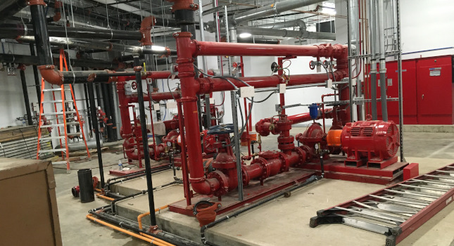
It is worthwhile to make sure the electrical and mechanical designers are familiar with their respective requirements for a fire pump room, but the most important item to start with is coordinating adequate space for the fire pump system and all related equipment that will be installed in the room. Dry/pre-action/deluge valves, air compressors and nitrogen generators (where applicable) and piping must be accounted for. Tall buildings with multiple fire pumps supplying separate vertical zones or projects requiring backup fire pumps obviously require more space in the room along with additional electrical power and fire alarm coordination points (see Figure 3).

Arrangement of the room is more important than total square footage, as nonrectangular shapes limit the efficiency of the space. Components such as structural columns and beams can infringe on the space; therefore, it is important that all disciplines on the design team are aware of the space requirements.
Incoming water services are also a factor. There may be a single combined water service that splits to the separate fire protection and domestic system backflow preventers or each system could be provided with a dedicated service. Along with this, the size of the backflow preventer varies greatly by diameter so the appropriate area must be accounted for.
For space requirements in the fire pump room, accurate dimensions of the controllers are crucial. A variable frequency drive fire pump controller with an automatic transfer switch may require a significant amount of floor area and wall space. Product data sheets are likely necessary to ensure dimensional accuracy. See Figure 4 for an example of a fire pump controller with VFD and automatic transfer switch.
Good practice supports consideration of a low-grade water supply condition along with a safety factor applied to the pressure calculations as part of a quality design. Disadvantages may include a larger power rating for the fire pump and the potential for pressure-reducing valves where they may not have been required otherwise. For situations where PRVs will be required throughout a building due to fluctuations in the incoming water supply or due to a pump churn pressure that is much higher than the rated pressure, a VFD controller may be beneficial.

Referring to the example above, Section 403.4.8 of the International Building Code (2018 edition) requires emergency power for an electric fire pump in a high-rise building. If emergency power is not available, a diesel pump may be more appropriate.
Electrical engineers typically favor soft start and VFD motor controllers due to the advantage over across-the-line starters when sizing the emergency generator. It is important that they understand the implications of the different starting methods. It is beneficial for the electrical designer to review product data sheets for the controller options and power requirements before finalizing the basis of design equipment.
In some cases, a VFD may allow for a smaller size emergency generator, saving space and considerable cost. VFDs may also reduce or eliminate the need for PRVs, depending on the specific situation. While a VFD fire pump controller may have significant benefits for some applications, it is not always an appropriate solution and should be discussed on a per project basis.
When a VFD controller is specified, the bypass type should be indicated as a soft starting type. This will satisfy the requirements for preventing higher than normal in-rush currents during bypass operation as outlined in NFPA 20 Section 10.10.3.
Keep in mind the type of fire pump specified and how the types differ. Diesel-driven pumps require additional provisions in the fire pump room such as ventilation, batteries, and a fuel tank. The fuel tank requires extra floor space that is not needed with an electric pump. A diesel fire pump may rely on batteries for starting, but an electric pump requires additional coordination with the electrical designer. They need to know the starting method and voltage for the particular pump. Nobody wants to hear about a 460-volt fire pump being delivered to the site when the building only has 208 volts available. A quick conversation during design can avoid that headache.

Fire pump coordination
The items below serve as a basic checklist of additional coordination items not previously discussed.
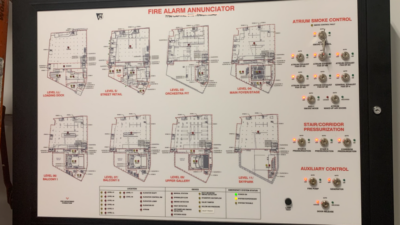
- Points on the fire protection system monitored by the fire alarm system such as fire pump status, control valve positions, waterflow and tamper switches.
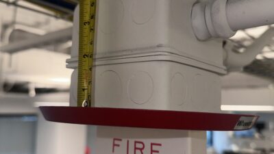
- The approved audible alarm device required per IBC 903.4.2.
- Floor drains shall be capable of handling the discharge from all sources including relief valves in recirculation designs.
- If flow testing is required, the design should account for how that can be achieved and how the flow can be drained accordingly. If water recirculates and a flow meter is used for the required flow test, refer to A.4.22.1.1 in NFPA 20. Recirculation can be a good method to conserve water, but a means of testing the water supply is still required at least once every three years.
- Location of the fire pump test header. Ideally, it would be located on the exterior wall as close as possible to the pump to limit the length of piping needed. Generally though, the driving factors are the preference of the owner and architect based on aesthetics and the constructability based on exterior wall design and use of the rooms bound by exterior walls.
- Coordination with the structural engineer may be needed for concrete pads.
The success of a project design can be measured in the number of RFI’s (requests for information) and changes that come up after the final submittal. Thorough coordination efforts with other disciplines are key to minimizing these changes.