Commissioning emergency power supply systems requires thorough knowledge of codes and several building systems
Learning Objectives
- Understand the basics of commissioning an emergency power system.
- Learn about the emergency power supply system sequence of operations.
- Cover the basics of when a power system is ready for commissioning.
The commissioning of complex emergency power systems requires the commissioning provider (CxP) to possess technical knowledge of applicable regulations, standards and codes in addition to considerable real-world experience with emergency power systems and integrated systems testing.
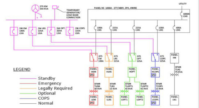
When discussing emergency power systems, it is important to understand a few key distinctions in equipment and system terms. NFPA 110: Standard for Emergency and Standby Power Systems defines emergency power supply systems (EPSS) as including the emergency power source (generator), distribution (such as paralleling switchgear) and transfer switches. Whereas the emergency power supply (EPS) includes only the emergency power source (generator) and any distribution upstream of the transfer switches.
Generator, genset, emergency generator or engine generator?
While it may have many commonly used names, the “generator” portion of the EPS is typically an on-site combination engine generator that is capable of providing a stable source of power to certain loads within a minimum required time.
Automatic transfer switches are devices that automatically transfer designated building loads between two sources of power, typically the utility company (primary or preferred source) and the EPS (secondary or alternate source). Startup of engine-generator and transfer of loads is usually automatic, but can also be manual where permitted by code.
The last major piece to an emergency power system is distribution equipment dedicated to the emergency system. An example of such equipment is a paralleling switchgear, used in distributing a shared load between multiple synchronized gensets. It should be noted that design may incorporate elements of emergency distribution equipment as needed, but the one common factor with all EPSS designs will be the on-site source or genset.
Commissioning the electrical system
Commissioning should occur during each phase of a project; early involvement provides additional advocacy for client goals, operations and maintenance values from design through construction and into systems turnover.
While the electrical CxP may provide peer review of the design in addition to other commissioning tasks, it remains the responsibility of the engineer of record (EOR) to adhere to construction standards and the local authority having jurisdiction enforcement requirements.
It is during the design phase that the CxP will begin to develop the functional testing pass/fail criteria for the EPSS that will demonstrate compliance with the design intent.
The CxP determines the design intent not only from the construction documents, but from the owner’s project requirements when available, the design EOR’s basis of design and perhaps most importantly, the EPSS sequence of operations.
EPSS sequence of operations
Perhaps the most important component of the emergency power system’s commissioning process is the sequence of operations. Simply put, the EPSS sequence of operations is the written description of what is intended to happen based on design, i.e., the sequence of events when utility power is lost and the restoration of utility.
While the concept may appear simple, the execution of design intent and functional demonstration can be complex, especially for emergency power systems with multiple paralleled gensets, multiple transfer switches and load shedding.
Too often these sequences are not included or mentioned in the construction documents or are developed late in the construction process. Without an EPSS sequence of operations, components may be set to factory defaults or programmable settings installed based on best practice by the manufacturer representative. In the event the CxP is without an EPSS sequence of operations, commissioning may be relegated to documenting as-installed conditions during the construction phase.
A typical EPSS sequence of operations may include the following:
Written description of operation: A description including all scenarios considered within design with relevant programmable settings. Typically begins with, “Upon loss of utility power the following shall occur…” and includes scenarios such as:
- Loss of utility power.
- Restoration of utility power.
- Loss of single and/or multiple generators.
- Restoration of generators.
- Overload condition(s).
Generator paralleling features:
- Generator demand add/remove, desired timeframes for engine-generator(s) to start, parallel sources, loads to transfer, optimize bus.
- Load shed: To add or remove load based on load priorities and load type. With load shed feature order of restoration of devices shed. Means for establishing restoration order can be sub-priorities, estimated load (kilowatts) and time delay.
- Breaker control scheme, with main-tie-main bus configuration or double-ended emergency power bus with tie-breaker.
Transfer switch features: Programmable settings and time delays to ensure proper system startup and operation, including:
- Engine start delay.
- Delay to transfer to alternate (emergency) source.
- Delay to retransfer once primary (normal) source is restored.
- Engine cooldown.
- Bypass isolation.
Construction phase
When developing the functional performance tests for new emergency power systems, the CxP should consider not only the design engineer’s proposed sequence of operations but also project-specific aspects such as construction and installation phasing, scheduling and other unique requirements of EPSS equipment.
The EPSS sequence of operations is considered perhaps the most important design element used to develop the EPSS functional performance tests. This, as with other functional performance tests procedures, should be developed by the design EOR and included in the construction documents.
The EPSS functional testing process typically involves first testing individual components unique to each emergency power system, such as the engine-generator, batteries, fuel system, transfer switches, etc. Only when all of the individual emergency system components are successfully commissioned should the CxP move on to demonstrating the overall EPSS functional performance tests.
Startup schedules significant to commissioning an EPSS should be identified and discussed during the commissioning kick-off meeting. These milestones, along with other commissioning activities with durations, are typically represented in the project’s construction schedule, which is maintained by the general contractor or construction manager. The CxP should collaborate with the construction team and provide input on these commissioning milestones.
When is ‘ready’ actually ready?
As CxPs, we are often told by installing contractors that the systems are “ready for testing.” But experience teaches us that “ready” may not mean the same thing to everyone, so the CxP may benefit from a more specific application of this term as it relates to the installation of EPS and EPSS equipment. Establishing a common definition for “ready to commission” or “ready for testing” with the on-site team and installers may avoid miscommunications, wasted trips to the project site and expensive retesting.
While every project design and installation is unique, applicable construction standards and manufacturer’s installation requirements should be referenced when possible, below are typical rules of thumb to check for when determining if EPSS components are “ready for commissioning.”
Ready for commissioning: engine-generator
- Generator, housing, silencers, batteries and annunciators are installed.
- Feeder conductors are terminated, torqued, labeled and document megger testing results. Reports submitted.
- Grounding is complete. Ground resistance tests/reports complete. Report submitted.
- Labeling/instruction sheets provided per specifications.
- Louvers, dampers, air supply and exhaust systems are installed and operational.
- All doors, walls, screens, etc. that make the generator room or enclosure are installed and complete.
- Phase rotation verified to match the utility.
- Utility voltage verified to be within an acceptable range for transfer.
- NFPA 110 compliant remote annunciator panels installed. Wiring run. Panel operation verified.
Ready for commissioning: fuel systems
- Main fuel tank installed. Low- and high-fuel level sensors installed and set for desired level to activate pumps.
- Fuel supply pumps installed, wired and tested by contractor.
- Day tank(s) installed. Low and high fuel level sensors installed and set for desired level to activate pumps.
- Fuel return pumps installed, wired and tested by contractor.
- Fuel oil piping is complete and operational (no leaks). Directional arrows and labeling provided.
- Shutoff and bypass valves installed and labeled.
- There is sufficient fuel for testing.
- Remote fuel system panels, alarms installed and wired.
Ready for commissioning: paralleling switchgear
- Switchgear is installed in a climate-controlled room when specified.
- Labeling per specifications. ATS names on the operator interface terminal match the electrical drawings.
- Breakers set per the approved coordination study.
- Breakers have been International Electrical Testing Association tested. Report provided.
- Breaker plugs match the electrical one-line drawing.
- Breaker fault current ratings are per the electrical drawings.
- Processor is programmed per specifications. Processor settings are submitted and approved by the EOR. Any deviations are approved by the EOR.
- Processor settings not originally provided by the EOR are verified by request for information.
- Priority settings are provided and installed per the EOR.
- Load shed/add delays and or sequence are provided and installed per the EOR.
Ready for commissioning: ATS
- Conductors are terminated, torqued, labeled and document megger testing results. Reports submitted.
- Vendor startup testing is complete. Report provided.
- Generator start/stop wiring installed and verified.
- Processor and time-delay settings are programmed per sequence of operations and specifications and approved by the EOR. Any deviations are approved by the EOR. Settings not originally provided by the EOR are verified by Request For Information.
- Priority settings are provided and installed per the EOR.
- Load shed/add delays and or sequence are provided and installed per the EOR.
Ready for commissioning: equipment connected to the EPSS
- Life safety and critical branch panelboards are powered.
- Essential and nonessential panelboards are powered.
- Chillers, boilers, pumps, air handlers are operational.
- Any elevators, fire alarm, security, smoke evacuation, uninterruptible power supply/computer, TV, telephone or other special systems are powered.
- NFPA 110 load bank testing has been completed. Report provided.
Acceptance phase
Once all of the individual components of the EPS, transfer switches and electrical distribution have been successfully tested, full functional performance testing of the complete EPSS and building-wide integrated systems testing, can be performed.
EPSS commissioning: In addition to design criteria and sequence of operations, NFPA 110 Chapter 7.13 Installation Acceptance (written as code language for an installing contractor to demonstrate compliance to an authority having jurisdiction) is often used as a reference standard by the CxP when developing EPSS functional performance tests.
Where design criteria and construction standards conflict, the more stringent of the two should be observed unless documented direction from the EOR and/or authority having jurisdiction is provided stating otherwise. The EPS or genset(s) would then later be demonstrated as integrated with other EPSS components, such as transfer switches and/or paralleling switchgear.
While the intricacies of an EPSS test are too numerous for elaborating here, the major steps typically include the following:
Typical EPSS testing steps:
- Ensure all system components are in auto/ready position.
- Simulate normal power outage.
- Ensure generator(s) start.
- Verify transfer switches transfer. Record transfer times.
- Verify paralleling, load sharing, if applicable.
- Verify emergency loads are operating.
- Test load shedding, load prioritization.
- Restore normal power.
- Verify retransfer times.
- Verify engine cooldown.
Contractor participation in commissioning EPSS:
- Electrical contractor: Available on-site to answer any questions, make necessary adjustments or energize/de-energize equipment if necessary.
- Generator vendor: Technician who has knowledge of the generator engine who can answer questions or make adjustments if necessary.
- ATS/paralleling switchgear vendor: Technician who has knowledge of the ATS and paralleling switchgear who can answer questions and make programming adjustments if necessary.
- Installer: Project manager who can provide a testing schedule and coordinate subcontractors; Available to answer any questions.
- Control contractor: Technician who has knowledge of the project’s building automation system and demonstrates all sequences.
- Mechanical contractor, piping: Available on-site to answer any questions or make necessary adjustments if necessary, to the fuel oil piping system.
- Mechanical contractor, sheet metal: Available on-site to answer any questions or make necessary adjustments if necessary, about air supply and mechanical equipment operation.
- Facility maintenance personnel: Welcome to observe testing to gain knowledge of the systems. Considered free training.
Integrated system testing
Integrated system testing should be applied when considering commissioning an emergency power system. Initial commissioning efforts can be described as verifying the components while later efforts should focus on the interoperability of all of those components working together to comprise the entire emergency power system. Commissioning involvement throughout the installation process, verifying the components of a system operate ahead of system testing, inherently mitigates risk: identifying issues sooner rather than later.
After a successful demonstration documenting installation meets design intent for individual building systems — heating, ventilation and air conditioning (HVAC), lighting, hot water, fire alarm, etc. — typically performed under utility power, then integration of whole systems should be performed, with those systems operated under emergency power conditions.
For example, to begin the emergency power integrated system test for the HVAC systems, begin with the HVAC systems operating under normal building conditions and simulate a loss of utility power (sometimes referred to as a black-site or dark-site test). This will provide an integrated system test for the EPSS and HVAC systems simultaneously.
Once the HVAC integrated system test performance has been verified and while still in dark-site test mode, additional system integrated system testing can be performed:
- Fire alarm test.
- Elevator tests.
- Emergency lighting tests.
- Emergency communication systems tests.
- Fire pump/life safety systems tests.
These integrated system tests would typically be performed as a last construction phase commissioning activity. If these systems can perform as expected after being transferred to the EPSS — and back again — then the owner can feel confident they will operate as expected during an actual emergency event.
Existing EPSS testing
Commissioning of an existing EPSS with new components presents additional challenges, but the approach of demonstrating parts of a system before the whole remains the same. The owner and facility manager are integral in defining successful test results and coordination of commissioning effort. The core challenge is how to eliminate or minimize affecting occupied spaces while successfully demonstrating the EPSS in near or close to normal operating conditions.
Some of the points to discuss with the commissioning team to help provide the owner and facility manager confidence in the commissioning approach are as follows:
- Identify which loads may not experience an interruption in service (ATS serving uninterruptable power supply or IT equipment, fire pumps, etc.).
- Identify which loads must have interruption in service minimized (ATS serving air handling units with long startup cycles, etc.).
- Identify which loads may be affected.
- Establish a backout plan; in the event of an actual power outage, the steps necessary to exit testing and restore normal operating parameters.
Successful commissioning
The commissioning methodology presented here is intended to aid commissioning providers — and all commissioning team members — in identifying the most important steps in commissioning of emergency power systems. As is true when commissioning any building systems, advanced planning and well-defined expectations based upon design criteria, sequence of operations and owner requirements are key elements to ensuring successful outcomes.
The commissioning plan should clearly define these requirements as well as “Ready for construction phase commissioning” expectations and integrated system test procedures described above.
Definitions
Legally required system: NFPA 70: National Electrical Code definition denoting, as the name implies, an emergency power system that is required by code.
- Level 1 system: Designation defined by NFPA 110 of an emergency power system where failure of the equipment to perform could result in loss of human life or serious injury. In most cases, legally required systems are considered Level 1 systems.
- Level 2 system: Designation defined by NFPA 110 of an emergency power system where failure of the equipment to perform is less critical to human life and safety. Often optional standby systems are considered Level 2 systems.
- Optional standby system: NEC definition denoting an emergency system that is not required by code but is provided to give additional (optional) emergency power capabilities to a facility.