A harmonic analysis to study system operation and mitigation methods of a design-build wastewater treatment plant was conducted in April 2015 in Boston.
A harmonic analysis to study system operation and mitigation methods of a design-build wastewater treatment plant was conducted in April 2015 in Boston. Performance testing was completed at the wastewater treatment plant located in Washington, D.C., after substantial completion in March 2016.
Active harmonic filters used to mitigate harmonic distortion, and performance testing was completed under multiple operating scenarios using Power Analytics DesignBase software.
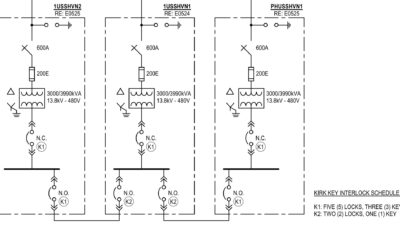
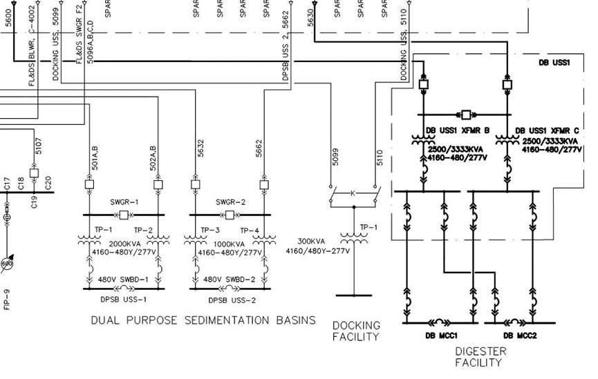
This project involved extending 4,160-volt campus power distribution to several new facilities. Each facility was provided with a unit substation to reduce voltage to 480 volts, 3-phase. Each unit substation distributes power to a variety of 480-volt motor control centers. The wastewater treatment process includes redundant process trains for solids removal, dewatering, thermal hydrolysis and anaerobic digestion.
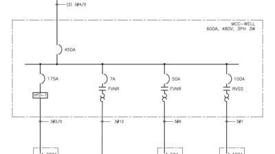
Due to the quantity of equipment needed to process the wastewater redundant 480-volt main-tie-main, MCCs are provided for the dewatering, thermal hydrolysis and anerobic digestion process trains. A single main-tie-main 480-volt MCC is provided for the solids processing train.
Variation and efficiency requirements for the process flow necessitated the use of variable frequency drives for a large percentage of the process motors. In addition to process load, mechanical heating, ventilation and air conditioning equipment for building conditioning included nonlinear load for fans and cooling equipment used to condition each facility. Variable speed motor horsepower ranged from 5 horsepower for small chemical pumps to 250 horsepower for dewatering centrifuges.
The majority of VFDs serving the process motors were packaged integral with the motor control centers. VFDs less than 50 horsepower were six–pulse pulse-width modulation design with 5% input line reactors. VFDs larger than 50 horsepower were required by technical specifications and owner standards to be 18-pulse design. Active front–end regenerative drives were used to control the large dewatering centrifuge main drives and back drives.
Each main-tie-main motor control center was constructed with redundant active harmonic filters. Under normal operating conditions, the MCC tie breaker is open and each active filter serves one-half of the bus. During maintenance, the tie breaker is closed and both active filters operate in tandem. Careful consideration of the current transformer placement (additional current transformers and wiring are required) is needed to allow redundant active harmonic filters to operate in a single-ended condition.
A preliminary harmonic study was developed early in the design phase to determine the rating of each active harmonic filter. Active harmonic filters are specified in increments of 50 amperes. The anaerobic digester facility was calculated to demand the most nonlinear load. An upsized active harmonic filter (100 amperes) was initially considered for the anaerobic digester MCCs but eliminated after completing a detailed harmonic analysis. The minimum size active harmonic filter (50 amperes) was selected and specified for each main on each main-tie–main motor control center.
A detailed harmonic study was completed after procurement of all equipment. The point of common coupling was chosen to be the 4,160-volt side of each substation transformer serving the process trains. Considering that future modifications to the 4,160-volt campus distribution were possible, the PCC was selected on the primary side of the distribution transformer. Distortion at each low voltage bus also was calculated to examine current distortion at the motor control centers. The results of the harmonic analysis were developed and reviewed for compliance with IEEE 519.
After substantial completion, a performance test was conducted to verify and document harmonic distortion throughout the system. The performance test included two scenarios. One scenario examined harmonic distortion under extreme process conditions (maximum demand). A second scenario examined harmonic distortion at 50% process conditions.
While not applicable to IEEE 519 goals, examining harmonic conditions at typical operation points is advisable to review performance under normal operating conditions. The results of the performance test were reviewed and determined to be in compliance with criteria specified.
Note that the analysis and testing performed for this case study were in compliance with IEEE 519-1992.