Use this as a guideline of terms, topics and tips for setting up work-shared Autodesk Revit project models.
Learning Objectives
- Increase the mechanical, electrical, plumbing and fire protection engineers’ understanding on how an Autodesk Revit model can be set up to allow for greater integration into the building design process.
- Learn basic concepts related to Revit project setup: relevant terms, process overview and best practices.
The focus on building information modeling (BIM) grows every year, and the importance of having a solid foundation on which to build each project has never been higher. This article will give the mechanical, electrical, plumbing and fire protection (MEP/FP) engineer some of the more basic concepts of Autodesk Revit project setup and provide insight to some of the more crucial concepts that will allow for greater external coordination or more efficient internal workflows.
Many of the concepts can translate from Revit to other design software tools and back again, however many of the Revit-specific terms and details will not.
Revit file types (project *.rvt, family *.rfa and template *.rte) are unique to each year or version of the software; they can be upgraded easily as needed but cannot be downgraded in any way. This can cause many problems but can be completely avoided by creating and maintaining all custom company content in the oldest necessary/supported year version. This can be dictated by client need or software license restrictions and it will be necessary to coordinate this with clients and information technology support staff and/or BIM team as the details of each project become clearer.
A rule to put in place with all users: Never double-click any Revit file to open it. The operating system does not recognize the difference or the importance of keeping these file types in the correct year and can give undesired results. Best practice is to always confirm the year version of the project before doing anything else.
The topics covered here are intended for creating and maintaining MEP/FP Revit project models using a work–shared central model. A central model is a Revit project file that has been saved to a central location, usually on a company network, that is accessed by multiple users simultaneously via local copies. These local copies are then synchronized back to the central model by the users as modelling and design work is completed. The collaboration and coordination that this enables is vital; engineers and designers from all disciplines within the model can coordinate system design in real time.
It will become clear after continuing through this article that Revit projects can be very complex and not only in size and scope. There are many separate entities all relying on each other and the data that is held within them. Company standards will need to be setup/adopted/adapted and during this process careful consideration should be made for both internal and external expectations.
Be deliberate and consistent when developing company standards, use short yet descriptive names for any content and adjust workflows or expectations with clients when faced with limitations. The intention is to maintain clarity not only for the clients but for the designers/modelers as well.
A BIM execution plan is an excellent way to communicate these expectations. This is a document that would contain information about the project model, level of development, milestone dates and any BIM-specific requirements or extra data. This is obviously a large amount of effort and time invested but it is a necessary step on the path to successful Revit projects.
We will proceed with the assumption that Revit project work is already occurring within your company, with standards and workflows defined. The topics covered here should grant insight to the setup process to use in conversations as client needs change and as custom company content gets refined.
Company content
Before a Revit project can be setup, company content must be in place. Three types of content include a project template, shared parameters and a library of typically used families. These three types will be described briefly before expanding on some of their finer details and how they can interact.
Project template: An ideal project template can best be described as clean. Template in this case is not referring to the specific Revit template file format (*.rte) but rather a Revit project (*.rvt) that has been created and configured to be transplanted to each project folder during the initial model setup. This project template should begin as an out-of-the box Revit project that will need to have its settings modified based on several factors, such as:
- Company standards.
- How many and what type of systems will be modeled.
- Project and/or client requirements.
The project template will also contain items like worksets, filters and view templates. These are all items that will control the visibilities of elements within the model.
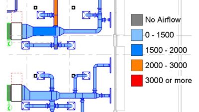
View templates set up within the project template are an essential tool to easily maintain visual fidelity across any desired views within a Revit model. They control individual visibility settings and can be set to include or exclude each setting. The visibility settings of linked external models also can be set via view templates, which is what allows the MEP/FP Revit model to control the display of background elements separately from the MEP/FP design elements.
View template properties also can be applied to views without “locking” the template to the view. “Apply template properties” sets all the defined settings to their specified values but then allows the view to be modified independently afterward. View templates offer a wide variety of view control that can be used in interesting ways. One method to maximize the use of view templates is to create categories of view templates to manage only specific settings. Categories could include filters, links, view ranges, visibility graphics and worksets.
Each category would be named appropriately, perhaps by type of plan views that would require a view range adjustment or by worksets required to be visible based on discipline. These templates could then be applied in a sort of layered way by selecting all appropriate views at once and “applying template properties” or even just applying a single view template.
Shared parameters can seem daunting — no doubt it is a very large task to generate a standardized list of any parameter that might be necessary for all the separate disciplines that will be expected to be modelled in a Revit project. This necessary task provides the actual link between families, their tags and schedules. It is the same parameter loaded from the external shared parameter file into each of those items that makes this possible.
To provide some freedom to the designer/engineer/modeler, evaluate shared parameters that should be calculated values and some that should be just plain text or informational only. All parameters are defined with categories and expected values, these expected values can cause undesirable results when tagging or scheduling equipment. As an example, a shared parameter set to display the temperature as degrees Fahrenheit cannot be overridden to a dash or other character within a schedule or tag as it will expect an integer input only.
Library of families
The library of families should contain the families that are used most often by each discipline: receptacles, diffusers, sprinkler heads, tags, title blocks, etc. The families should also be kept as clean as possible. “Clean” means free from any unused materials, parameters, styles or any other unwanted excessive geometry.
Any family with geometry should be modeled accurately, yet not overdone. Families with excessive detail can be detrimental to model performance. Each project also will require families that are either not yet created in the library or that are specific to a manufacturer which generates their own. These will need to be reviewed on a case-by-case basis, if not to adjust or purge unused data but also to ensure that the proper shared parameters are included to allow for any calculations, tagging and/or scheduling.
Setup process
The project setup process begins by opening the proper year version of Revit for the project, then opening the project template with the work–sharing option set to “detach from central” and finally selecting the next available option of “detach and preserve worksets.” This will sever the link between the Revit project being created and the old central file (in this case, the project template) and allow the new model to be setup as a Revit project central model.
Once the Revit model has finished loading and/or upgrading it can then be saved to the proper project location and renamed with a standardized file name. The file name will typically be a short description of the project followed potentially by what type of Revit model (MEP/FP in this case) and the year version of the file (as an example: ProjectName_MEP_v2018.rvt). Naming conventions like this are used in a variety of ways and the intent is to provide enough information in the file name to allow any other project team member to easily identify exactly what kind of Revit model they are working with, especially helpful when dealing with many links within the same project.
The final step to establishing the central model is to synchronize changes, relinquish borrowed elements and then close the project. The new project model should now only be opened by ensuring that the work–sharing option is set to “create new local.” If this option is greyed out or otherwise unavailable when a Revit project is selected within the open dialog box, this could mean that there may be an issue with the model or that the year version is not compatible with the currently open version of Revit. If unsure about the status of a Revit model, get in touch with any specified model coordinators immediately to avoid any possible issues like loss of work.
Links and link types
Revit models received from outside sources will be used to create the two-dimensional annotation and three-dimensional geometry background elements for the MEP/FP model as links. This is done by creating a file path link to the external model, most commonly architectural, structural and potentially other specialized consultant models such as food service or lighting design.
Revit allows several types of files to be created as links: other Revit projects, industry foundation classes, CAD formats (most commonly AutoCAD DWG), design web format markups, point clouds and topography files. The file types most used by MEP/FP Revit models will be other Revit project files and CAD formats.
CAD links should be used only to serve a small, project-specific purpose — if at all — as they provide no intelligent linking of data. One situation where CAD links seem to work well are as a site plan within the architectural model. The nature of a site plan is more about project location and less about actual building design, thus much less time and effort should be used to generate these plans. Using CAD links for site plans works so well because Revit will maintain the last known visibility of a CAD link even if the drawing file was not included when files were exchanged. Revit will display the status of these CAD format files in red color as “not found” in the manage links window. Best practice is to evaluate all links within any models received from external sources before linking them into the MEP/FP model.
Creating a link
The MEP/FP model should be opened as a local copy, ready to add the necessary links. All models intended to be used as links should be set with reference type set as “overlay” and located properly within the model. The overlay option does not allow the link to be displayed when the host model is linked into another model, unlike attach, which produces the opposite effect. The reference type set to overlay will prevent any unwanted issues from occurring.
The links should then be pinned and set to the correct workset and/or design option according to company standards. The architect may have used phasing on the project; this will need to be verified within the phase settings and phase filters of the architectural model and modified within the MEP/FP model to match if applicable. The architectural link would then need to be modified by selecting the link and choosing “edit type” in the properties window. This will open the type properties window for the selected link with type parameters displayed in a table.
Phase mapping can be edited here to match up the phases that exist within the MEP/FP model to the phases that exist within the link. The room bounding value also should be checked to before clicking OK to apply the changes, this allows room and space data to function properly with the linked model.
Copy/monitoring link data
This is the point where the reliance on the architectural model greatly increases. Crucial items will begin to be generated within the MEP/FP model via the copy/monitor tool within the collaborate tab of Revit. These crucial items should at the least include levels and can include any item that would need to exist within the MEP/FP model, but also still be dedicated to the information provided by the architectural link, grids being an example of this.
It is a great benefit to establish with the architect what elements are being monitored within the MEP model so that any architectural changes can be expected before ever opening an updated model. If a change is made in the architectural link that affects a copy/monitored element within the MEP/FP model, upon reloading, the link Revit will display a warning prompting the user to perform a coordination review. The coordination review window will allow the user to select different courses of action, depending on what type of modification was made and what type of element was being monitored.
Best practice is to coordinate levels and grids with the architect as early in the project planning phase as possible, mostly to avoid issues that can become catastrophic when a level has been modified heavily or deleted.
Creating sheets
At this stage of the setup process, sheets can be generated using either a company standard title block or the project-specific title block extracted from the architectural model. The sheet name and number conventions will depend on the project or on company standards, but typically can follow the architect’s conventions with the discipline’s abbreviation replacing the architect’s.
A full set of sheets will need to be generated for every discipline working within the model. This is a manual task that can be very time–consuming on any projects that contain many sheets as the sheet creation tool within Revit only allows for the creation of one sheet at a time.
One method to speed up this process is to manually create the entire list of sheets for one discipline and then copy/paste those sheets within the project for as many disciplines as need to be created. Within Revit, the copy/paste process for sheets does not function as expected when using the default keyboard shortcuts of CTRL+C and CTRL+V. To copy sheets, navigate to the modify tab, select all applicable sheets and click the “copy to clipboard” button.
To paste the sheets into the project, click on the “paste from clipboard” button. Copy/pasted sheets retain most of the properties assigned to them originally, meaning any properties that are shared between all disciplines will not need to be modified again. Any properties that must be different for each discipline, like sheet numbers and names, will still need to be modified to the appropriate information.
Views and view types
Before going over the process to create views, it is necessary to break down the different view types — plan views and drafting views. Plan views display model background geometry as two-dimensional plans. Drafting views contain only annotation elements. Drafting views are usually used for design details or other items that would need to be included in the sheet set but are not plan views.
The plan views tool located within the view tab of Revit will allow the creation of floor plans, reflected ceiling plans, structural plans, plan regions and area plans. Typically, the view types necessary for an MEP/FP Revit model will be floor plans and reflected ceiling plans. Revit identifies floor and ceiling plans separately from each other. The cut plane within the view range property of each view looks downward to display the floor plan views and upward to display the reflected ceiling plan views.
Creating views
Like the process for creating sheets, views will need to be generated within the model. This is also a manual process that is affected by large projects in the same way that only one new plan view can be generated at a time. The method to speed up this process is also like the sheets in that it is beneficial to create all views for one discipline and then use those to create all the rest of the views, but unlike copy/pasting sheets, views can only be duplicated.
This is done by selecting a single view with a right-click and hovering over the duplicate view option to then select the duplicate with detailing option. Duplicate with detailing will create a new copy of the view, retain the same properties and add “copy 1” to the end of the view name. “Duplicate” will do this as well, but will not retain any annotations within the view; items such as tags, text, annotation–only linework, etc.
Duplicate as dependent creates the new view with a dependency on the parent view, any changes that are applied to the parent view are also immediately applied to any dependent views associated. Dependent views are used when dealing with projects that use partial plans with named areas. A view can be generated to show an entire level, then dependent views created for each area/sector that is defined by scope boxes to show only the appropriate area of that level.
After selecting the appropriate plan view to create, the new plan window will allow the selection of a level (copy/monitored earlier from the architectural model link) on which to create a new view. Once a view is created, the level cannot be changed, the view would need to be re–created using the appropriate level. Each view should have its properties modified to match the intent of that plan view. This can include properties like scale, detail level, discipline, view template, scope box, view range, etc.
Now that views are created, they will need to be placed onto the appropriate sheet. Once again, this is a manual process that involves selecting a view and dragging that view onto the corresponding sheet. The location of any item placed onto a sheet (view, view title, graphic scale, north arrow, etc.) would be determined by either the locations of these same items on the architectural sheet or by company standards.
Revit integration
The last steps to completion include verifying that all project information is accurate, all views are placed onto the proper sheets, all views have the proper phase settings and there are no other errors or issues with the model. The team should verify accuracy before the model is filled with design work and changes would become more difficult.
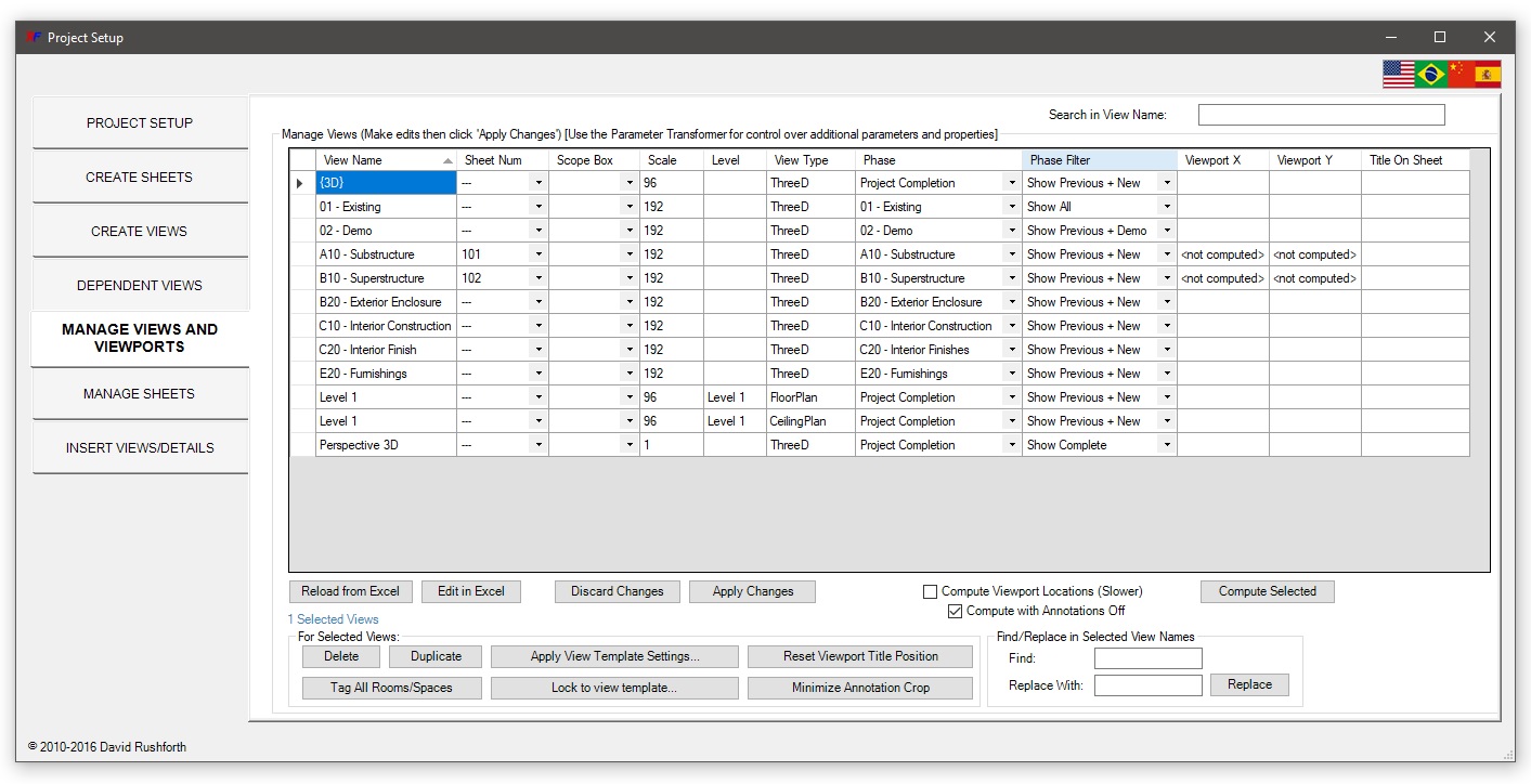
Many of the most time-consuming steps involve the creation of sheets, views and view management. The alternative methods mentioned for some of the steps (copy/paste, duplicate, etc.) are built into Revit and require no additional add-ins or plugins. That said, there are many tools available that are capable of automating steps within the process. Two examples of purchasable plugins include RushForth Projects tools and CTC Software tools. Both of these tools use the manipulation of parameter data to automate some processes. The best example of this is the capability to mass–create sheets and views and then place the views onto the sheets at specified coordinates.
These plugins also include many other tools to manipulate parameter data using Microsoft Excel spreadsheets and loading that data into Revit. Plugins like this can be extremely powerful not for just project setup tasks but also anything that would need to have parameter data modified in a batch, such as creating discipline schedules.
There are some free tools available as well, but these require some preliminary learning. Dynamo Studio is a visual programming tool that is capable of manipulating model data and has been included with Autodesk Revit installations for the past few years. Worth mentioning but much more complicated, the Revit application programming interface provides the bridge between model data and the C# programming language. This is what provides the foundation for the purchasable plugins mentioned above, and also can be leveraged by anyone with Revit and C# knowledge to create custom tools or utilities.
With the grasp on Revit setup terms and processes, the hope is that this knowledge can be used to guide client conversations or coordination in earlier stages of the project life-span to ensure project success for all teams involved.