Expanding our understanding of line and low voltage wiring to improve our decisions regarding the choice between automatic and manual lighting controls, while also considering code requirements.
Lighting control insights
- Lighting control plays a crucial role in optimizing energy efficiency and ensuring compliance with various codes and standards, including IECC, ASHRAE 90.1 and NFPA 101.
- Understanding the differences between line-voltage and low-voltage lighting control systems allows designers to select the best approach for balancing functionality, installation costs and future adaptability.

It is essential for electrical and lighting designers to have a fundamental understanding of code requirements and key considerations before starting the lighting design process. These factors include design specifications, building types, budget constraints and the minimum code requirements. Additionally, designers should consider the owner’s preferences regarding the type of system, understand the functionality of different spaces or rooms within the building, decide between 120 V and 277 V for lighting circuits and controls and address end-user requirements.
Lighting codes and standards
Codes and standards to consider and understand while designing lighting and controls:
- International Energy Conservation Code (IECC)
- Illumination Engineering Society (IES)
- ASHRAE Standard 90.1: Energy Standard for Buildings Except Low-Rise Residential Buildings
- NFPA 101: Life Safety Code
- NFPA 70: National Electrical Code (NEC)
- U.S. Green Building Council
- Applicable local codes and amendments
The IES helps designers determine the necessary level of illumination for different spaces, considering factors such as the type of work area, whether it’s an indoor or outdoor space and specific task lighting requirements based on the functionality of these environments. In addition, the IECC and ASHRAE 90.1 provide guidelines on lighting control sequences, specifying where and how automatic and manual controls should be implemented to maintain the desired foot-candle levels.
Understanding the difference between line-voltage and low-voltage lighting systems
Line voltage refers to the standard electrical connection used in lighting systems, typically ranging from 120 V to 277 V. The most basic example of line-voltage control is a manual on/off toggle switch, which opens and closes the circuit to either allow or interrupt the flow of electricity. Over the years, wiring has developed to include features that not only turn lights on and off but also offer a range of dimming options.
This system includes both a ground wire and a neutral wire, which are essential for multi-way applications. Line-voltage systems enable lighting fixtures to be grouped via switch legs, allowing the creation of control zones based on user preferences and code requirements.
There are several advantages to using line-voltage systems. Electricians are generally familiar with line-voltage wiring, which helps reduce installation errors. Additionally, these systems can be installed over longer distances, making them an excellent choice for retrofit applications during renovations or expansions, provided they are installed and used correctly.
On the other hand, line-voltage wiring has certain limitations when in terms of flexibility and control capabilities. Traditionally, it involves higher labor costs due to the complexity of installation. Costs can vary significantly based on certain circumstances, including fluctuations in copper prices.
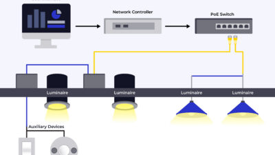
Breaking down low-voltage lighting control systems
Low voltage lighting controls are commonly used due to the widespread application of LEDs. Unlike 120 V to 277 V systems, low voltage wiring operates at 12 V to 24 V, supplying power and communication via data cables to low voltage control devices.
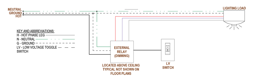
Low voltage systems typically include a power component that connects to manual control devices, such as wall switches or sensors, through either a wired cable or a wireless protocol. The power component should preferably be placed in an accessible ceiling within the same room as the lighting loads it controls.
When low voltage systems are connected wirelessly, typically one component will require a line voltage connection, while other devices often operate on batteries and do not need physical wiring. It is essential to note that all devices in a low voltage system should come from the same manufacturer and use the same communication protocols to ensure efficient functionality.
While most codes allow for low voltage wiring to be run without the need for conduits or junction boxes, making it independent of power systems and wiring, it’s important to check with local codes before design. It is also important to note that the NEC requires all low voltage wiring to be class two compliant for indoor circuits. This requirement helps prevent the risks of electric shock or overheating in indoor applications and mandates that 120 V wiring be segregated from 12 V to 24 V systems. This rule applies to both retrofit and new construction LED systems.
With dimming becoming a preferred control capability, manufacturers are offering dimming drivers that are compatible with a range of their products. Allowing users to dim light fixtures from a range of 0 V to 10 V down to either 10% or 1%. The ability to dim down to 1% is especially desirable in imaging spaces within many health care facilities.
Additionally, both commercial and residential buildings benefit from the smarter control options provided by low voltage systems, such as Bluetooth functionality, which enables users to control lighting and other building systems conveniently from their electronic devices.
Like any other system, low-voltage wiring has a few disadvantages that may cause owners and designers to reconsider this option. The facility/owner is tied to one manufacturer, preventing the option of having competitive pricing from other manufacturers for future projects or expansions. Other drawbacks include a higher likelihood of miswiring, increased material costs and the potential for unshielded conductors to pick up electrical contaminations from nearby conductors.
Selecting the right voltage
Both a 120 V or 277 V connection are integrated into the lighting system, allowing the owner to choose their preferred voltage system. This choice primarily affects the maximum wattage capacity of the lighting circuit.
Traditionally, lighting circuits are connected to a 20 A breaker, even though the code limitation is to not exceed a 50 A breaker for a lighting circuit, per NEC section 210.23(D). According to the NEC section 210.20(A), the calculation for overcurrent protection on branch circuits considers the sum of noncontinuous loads plus 125% of the continuous loads, and lighting is usually considered a continuous load, limiting the continuous load to 80% of the circuit breaker’s rating.
Breaking down this code language, a 277 V lighting circuit can handle 4,432 VA = 277V x 16A (80% of a 20A breaker) of lighting load. In contrast, a 120 V circuit is limited to 1,920 VA = 120V x 16A (80% of a 20A breaker). Therefore, it’s advantageous to use 277 V circuits by reducing the number of circuits needed while maximizing capacity of a single lighting circuit.
In the past, using a 30 A breaker was common because non LED fixtures, such as low-pressure sodium or metal halide lamps, had higher wattage per fixture. The 30 A breaker could accommodate a greater number of fixtures on one circuit due to this higher wattage. However, LEDs consume significantly less wattage per fixture, allowing for an equal or greater number of fixtures to be connected to a 20 A circuit.
Due to code requirements and regulations, it is essential to address voltage drop concerns. This is why, in recent times, site lighting is occasionally connected to a 30 A breaker. These setups must comply with code requirements, which help eliminate concerns regarding voltage drop, especially for longer runs to exterior site lighting.
Connecting lighting to a 30 A circuit also necessitates upsizing the wiring. This can pose issues, as the internal wiring of many LED fixtures is typically smaller than 14 AWG, making them more susceptible to overloading and short circuits. Such conditions can lead to fire hazards if these fixtures are connected to circuits exceeding 20 A. The NEC requires lighting connected to circuits above 20A to be equipped with heavy-duty lamp holders and compatible components.
It is important to note that while switching between 120 V and 277 V circuits can increase total wattage or VA, it is neither common nor recommended to upsize the breaker size beyond 20 A for lighting circuits, given the lower wattage per fixture that LEDs provide.
Defining an area of control
After selecting the voltage and control systems, the next step is understanding the various spaces and user preferences for controlling those areas. So, how can this be accomplished?
Start by defining areas of control, which is essentially specifying a group of lights that will be managed together, meaning they will all turn ON, OFF or DIM simultaneously. This grouping is typically designed to meet client or owner needs while complying with the energy codes that govern control areas.
Understanding and implementing energy code requirements
While planning and setting up a control sequence for lighting is mainly derived from user preference, that is not the only deciding factor. Codes and standards heavily influence whether these areas are to be manually or automatically controlled.
Most spaces are required by the IECC to utilize automatic controls to manage energy consumption and reduce costs. However, the same code specifically states that certain areas must be controlled manually. These areas are vital for the safety and security of building occupants, including exit passageways, stairways, exit ramps and paths of egress.
Where the code mandates it, manual controls must always be located where readily accessible to occupants and where controlled lighting is visible and manual control indicates or identifies what areas or lighting are connected to them.
Automatic control methods are primarily covered in the IECC and ASHRAE 90.1.
The first example is occupancy sensors, where lighting is automatically controlled based on the occupancy in a space, with occupancy sensors utilizing one of the following technologies:
- Passive infrared – dual technology.
- Ultrasonic.
- Microphonics.
Occupancy sensing is often integrally located to a lighting fixture, wall switch or ceiling/surface mounted device. In spaces where occupancy sensors are used, lighting is set to turn ON to 50% power capacity, automatically turn OFF after 20 minutes of unoccupancy and can be manually turned off as needed by the occupant.
In the areas where vacancy sensors are utilized, the lighting needs to be turned ON manually, but the vacancy sensors turn OFF the lighting within 20 minutes of the occupant leaving the room, providing an additional opportunity for energy conservation and savings. It is typically recommended in spaces where occupants might forget to turn off the lights as they leave a space.
Another example of automatic controls is a time switch control, where lighting is automatically controlled using a set schedule based on time and/or the day. A time-based schedule and control are required by code in spaces not provided with occupancy or vacancy sensing. In spaces controlled by time switches, occupants must be provided with an override switch complying with the requirements listed below:
- Shall be a manual control.
- The override switch shall not permit lighting to remain on over two hours.
- The override switch shall not control areas larger than 5,000 square feet.
- Lighting-reduction controls.
Lighting shall be provided with manual control to allow occupants to reduce the lighting load by at least 50% while maintaining a uniform illumination pattern or continuous dimming control as allowed by code.

Light reduction of the general lighting is not required where lighting is not controlled via:
- Occupancy sensors.
- Daylighting responsive controls.
- Luminaires provided for special applications.
- Areas that have a manual control under exceptions.
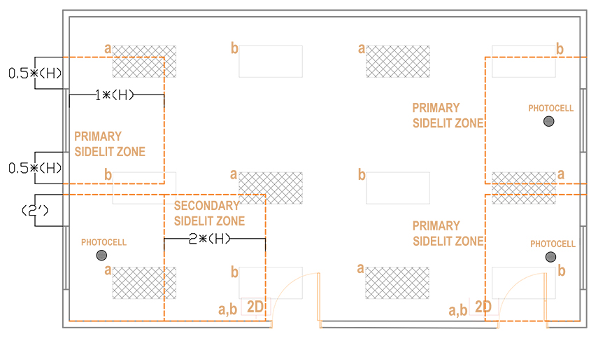
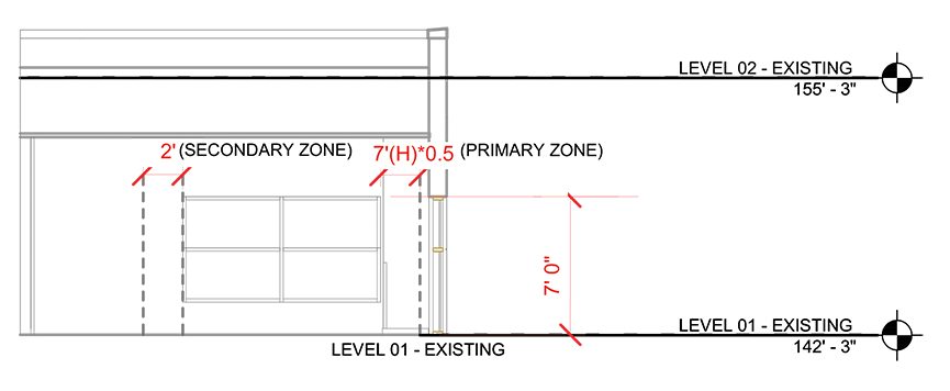
General lighting is automatically controlled based on the availability of daylight entering a space. Daylight-responsive reduction shall be achieved by photosensors (photocells) that can either be built into the fixtures or installed remotely. These sensors allow the lighting in daylight areas to turn on or off and adjust the brightness as needed.
Lighting fixtures falling within the primary, secondary side-lit zones and top-lit zones as specified in IECC and ASHRAE 90.1 shall be controlled when the total wattage in the primary zone exceeds 150 W. These daylighting zones are required to be controlled independently of one another.
If the primary daylight zone is under 150 W, the combined primary and secondary daylight zones are under 300 W or if the total glazing area is less than 20 square feet, then daylight-responsive controls are not required. However, these zones/areas shall be noted on plans. Another significant exemption from daylight-responsive controls applies to direct patient care areas in health care facilities.
Specific application controls
Where specific application controls are provided, the lighting in those areas shall be controlled by occupant sensor or time-switch controls complying with their appropriate code sections per IECC:
- Accent and display areas.
- Lighting in display cases.
- Additional task lighting, including permanently installed under-cabinet lighting.
- Lighting equipment in areas of sale for demonstration.
- Display lighting for exhibits in galleries, museums and monuments.
- Luminaires for which additional lighting power is claimed per IECC section C405.3.2.2.1.
Updated code requirements to incorporate in design
There can be significant differences between one code cycle to the other. and with more states and counties adopting the 2021 IECC or the 2024 IECC, there are a few updates that impact lighting and lighting control design.
One significant change from 2018 to 2021 IECC is the requirement for controlled receptacles. The updated code mandates that at least 50% of all permanently installed 125 V, 15 A and 20A receptacles in spaces such as enclosed offices, workstations and classrooms must be controlled. These receptacles may serve various equipment and portable devices including, but not limited, to computers, monitors, coffee machines, microwaves, convenience outlets and audiovisual equipment that do not have significant consequences from being turned off or losing power. Controlling these outlets when not in use or when occupants have left the area reduces additional power consumption.
Plug loads contribute as much, if not more, to energy consumption as lighting does. To effectively monitor usage, it’s important to consider the occupancy of a space or follow a predetermined schedule. Receptacles in these areas can be controlled alongside the lighting using occupancy sensors, time-switch controls or signals from other control or alarm systems. This approach helps us meet the requirements set by the IECC.
Time switch controls can be programmed for specific time periods and customized for each day of the week. This flexibility allows for the management of lighting and plug loads in designated areas of a building, based on operating hours, usage patterns and code requirements. A specific schedule can be implemented in an area in the building if it does not exceed 5,000 square feet and is limited to one floor.
Another effective way to manage controlled receptacles is by tying them into a wall or ceiling occupancy sensor that controls lighting in those spaces. These sensors can automatically turn off receptacles 20 minutes after the last occupant leaves the area.
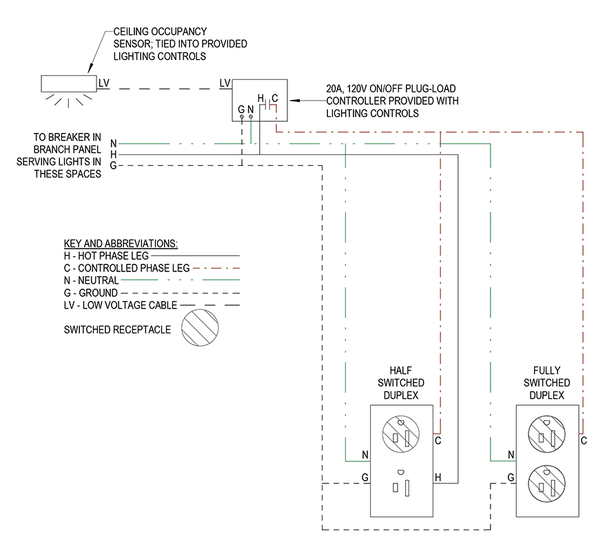
To prevent the loss of power to any equipment connected to a switched receptacle during unoccupancy, there are several options available. One option is to use a fully switched duplex receptacle, which has both outlets controlled by a switch. When selecting this option, one must provide an unswitched receptacle within one foot of the switched receptacle providing an uninterrupted power source for any essential devices. This ensures code compliance as well.
Alternatively, a half-switched or split-controlled receptacle can be employed, allowing one outlet to be controlled while the other remains continuously powered. This ensures that devices plugged into the continuously powered outlet receive 24/7 power. This approach can also be applied to quad outlets.
Occupant sensors in corridors
The 2021 IECC requires that corridors with lighting levels of two foot-candles or more at their darkest point must have occupant sensors.
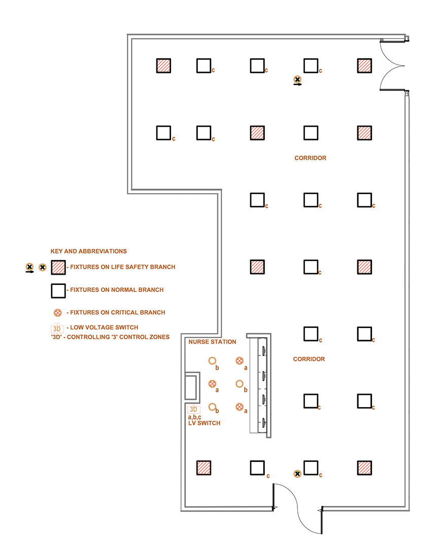
Applying these requirements in a health care setting can be challenging. Health care facilities typically use a combination of normal and life safety lighting because emergency lighting in corridors is required to provide the necessary illumination for staff and patients to safely exit the building in case of an emergency.
In these situations, it would be ideal to have manual controls with dimming capabilities, allowing staff to control the corridor and nurse station areas separately instead of relying on occupancy sensors. This preference is primarily because the light fixtures connected to the life safety branch of power remain ‘ON’ at all times, providing the necessary illumination for emergency exits if needed. This setup would also prevent lights from turning on and off due to occupancy sensing during night shifts, reducing the frequency with which nurses need to manually override these controls. However, since this approach does not meet code requirements, it must be verified with the owner and addressed with the authority having jurisdiction during inspections.
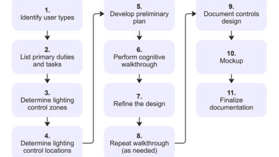
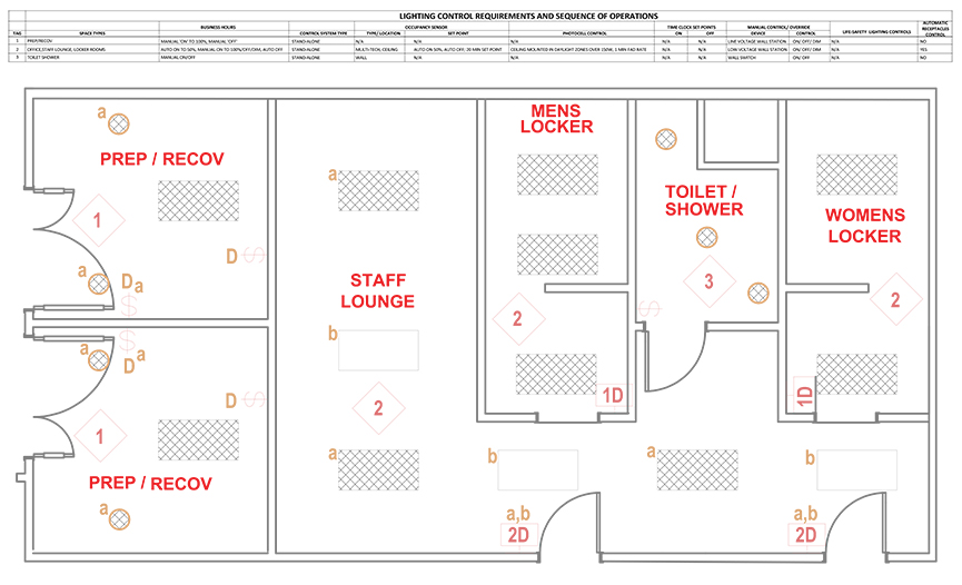
The final step in designing lighting controls is to coordinate and identify the necessary symbols and connections between the lighting and control systems on the plan. It is important to distinguish between line voltage and low voltage lighting control devices and to specify the locations and quantities of these devices. Additionally, control zones shall be indicated along with a sequence of operation table that accurately reflects how the space will be controlled.
In summary, lighting and lighting control systems involve a collaborative design process that requires interaction and coordination among electrical and lighting designers, architects and mechanical engineers. It is essential to discuss final ceiling heights, the placement of diffusers in relation to lighting and the layout of ceiling grids from both a spatial and locational perspective.
Once the basic design elements of the spaces have been established, selecting appropriate lighting fixtures becomes important, as well as understanding user preferences for controlling these spaces.
With advancements in the industry, it has become easier to integrate various systems for enhanced control by facilities management. Many systems can be interfaced with lighting controls on a room-by-room basis or for the entire building. This can include audiovisual systems, motorized shades, security and fire alarm systems and mechanical equipment.
While automatic controls help achieve integration of systems and are often required, certain areas allow for flexibility by code to use manual control systems. By optimizing lighting control systems based on room size, purpose and occupancy patterns, better working conditions can be created for occupants without compromising energy efficiency.