Learn to design power systems for mission critical facilities with a focus on ensuring redundancy and resilience in normal, emergency and standby power systems.
Learning objectives
- Understand the various code requirements for standby and emergency power for mission critical facilities.
- Learn strategies for power system redundancy and reliability.
- Review ways to make the power system more redundant and resilient.
Power system insights
- There are many building types that can be considered mission critical facilities. While “mission critical facilities” lacks specific definition within a code or standard, this building category can encompass buildings of diverse sizes and complexities.
- From fire and ambulance stations to large-scale manufacturing facilities, the critical nature and the level to which it must remain operational under all circumstances need to be carefully defined and designed for.
- Power systems are complex within mission critical facilities and must be designed to both meet code and achieve high reliability.
Various codes contribute to defining the minimum legal requirements for standby and emergency power systems; NFPA 70: National Electrical Code (NEC) Articles 700 Emergency Systems, 701 Legally Required Standby Systems and 702 Optional Standby Systems will always be applicable and provide foundational requirements but will be supplemented by additional codes based on the proposed occupancy type.
As mission critical facilities span a wide variety of use types, it is important to understand the different sources of codes and standards that may affect base requirements for emergency and standby power.
For those mission critical facilities that fall within health care, NEC Article 517 Health Care Facilities will become applicable along with NFPA 99: Health Care Facilities Code, NFPA 101: Life Safety Code and Facility Guidelines Institute guidelines, all of which will reference additional codes and standards that may affect the minimum requirements for the normal and essential power systems.
It should be noted that Article 517 amends Article 700, therefore Article 700 may not simply be replaced by 517; parts of 700 will still be applicable. Additionally, the Joint Commission publishes recommendations and requirements that they measure facilities against for granting hospitals accreditation. It is important to realize that these codes, standards and guidelines also define required periodic testing for the electrical systems, which will need to be carried out without interruption to facility operations.
Alternately, mission critical facilities that, if disrupted, “would disrupt national security, the economy, [or] public health or safety” (NEC Article 708.1, Informational Note No. 1) can be classified as vital infrastructure by governmental authorities, which will trigger compliance with NEC Article 708 Critical Operations Power Systems (COPS). Some examples of these types of facilities are:
- Emergency services such as 911 call centers, fire stations and police stations.
- Communications infrastructure including data centers and cell towers.
- Public utility plants.
It’s imperative to collaborate with the authority having jurisdiction (AHJ) over the facility because risk assessments must be completed to define the resiliency level required for the power system. Also note that the scope of Article 708 is not constrained to standby power only, but the entire portion of the power system that serves the designated critical operations areas.
Several facilities, however, fall outside of these classifications (i.e., not defined as strictly falling within the scope of Articles 517 or 708), but are still considered to be mission critical by either their stakeholders or the AHJ.
Generally, when an AHJ considers a facility or portion thereof “mission critical,” but not necessarily COPS, it is usually because the facility performs a function that, if disrupted, could pose a significant health and safety risk to personnel or the public. Power to those systems and processes would then fall under the requirements of NEC Article 701.
While we usually understand Article 701 to pertain to systems that aid first responders — stair pressurization systems, elevators, etc. — additional items that an AHJ could classify as legally required could be:
- Laboratory ventilation, including fume hoods and associated make-up air where hazardous chemicals or biological agents are handled.
- Systems required to maintain containment in biosafety level 3 and 4 areas.
- Systems required to maintain safe conditions within hazardous manufacturing areas.
It is important to determine and confirm a specific class and type of the emergency power supply systems required, as defined by NFPA 110: Standard for Emergency and Standby Power Systems, with the AHJ to understand the minimum requirements that will be applied to the project. Engineers must carefully research codes and standards such as the International Building Code, NFPA 99, NFPA 70, etc. and other industry-specific codes applicable to the project type to fully understand all baseline requirements.
Power systems beyond code requirements
Many mission critical facilities are considered as such due to the business interests of their stakeholders — if operations are interrupted, great financial damage could be incurred. Alternately, some government-run facilities may not be on a level to require COPS but are still considered critical to continue operation; one example of this would be a state medical examiner’s office.
In these cases, standby power requirements are defined according to NEC Article 702 and the facility owner’s requirements, but with the critical nature of the facility, the level of backup power will generally exceed what is strictly required by code. Owners frequently rely on engineers to define the appropriate levels of source and overall system redundancy.
Normal power system considerations
The facility’s normal power should be designed to achieve a high level of reliability to maximize power continuity for the entire facility as, generally, the on-site standby power source may only cover a limited portion. A regularly applied strategy for increasing normal power reliability is to receive two or more independent services from the utility service provider and arranging them so a single service or a combination of services can maintain the full capacity of the site.
Some best practices to consider when employing this strategy are:
- Request that the utility service provider (USP) provides circuits from different utility substations; the more independent the sources can be from one another, the greater the reliability we will achieve. A USP may even be able to provide feeds that originate from different power generation plants. Multiple sources should minimally originate from different utility transformers or buses so a single equipment failure does not disrupt both of the facility’s services and the service’s routing should be physically separated such that a single event does not damage both feeders. For example, if both feeders are to originate from the same utility substation, they should not be routed on the same poles or within the same duct bank.
- Incoming utility feeders should be routed underground as much as possible. As overhead services are more vulnerable to weather- and traffic-related incidents, feeders should be routed within reinforced concrete duct banks whenever possible. Spare ducts should be provided to facilitate faster feeder replacement in a catastrophic event (i.e., a cable fault) or for general end-of-life replacement.
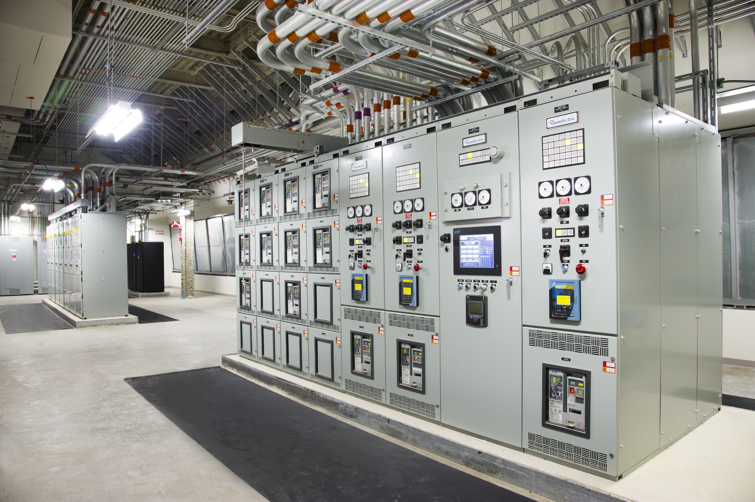
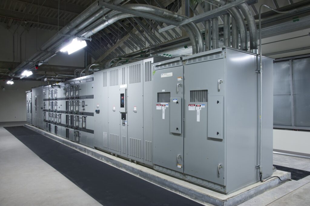
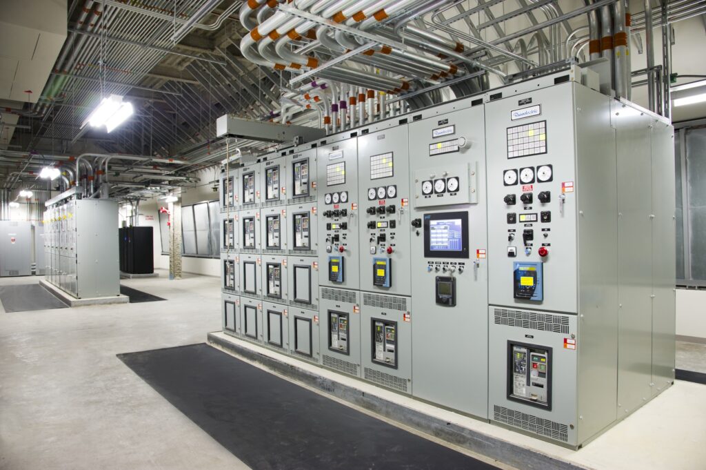
- Incoming services should terminate on separate switchgear line-ups. When receiving multiple services, the service entrance switchgear should have an independent bus for each service that is electrically segregated in a main-tie-tie-main fashion. This type of arrangement allows facility loads to be normally split between each service and, if a given service is lost, the switchgear will automatically open the associated main breaker and close the tie breakers to restore power to all service entrance buses. An alternate scheme could be a “primary-alternate” arrangement where all loads are normally served by one service and if that service is lost, the switchgear automatically switches to the second service. However, the main-tie-tie-main arrangement offers higher redundancy because both the incoming service and the service entrance switchgear are redundant. Additionally, the dual tie breakers, as opposed to a contiguous line-up with one tie breaker, allow for complete bus isolation and some degree of physical separation of the line-ups, which will better isolate faults or facilitate maintenance and repairs without exposing personnel to risk of arc flash events.
Careful consideration should be given to the downstream distribution system now that there is increased reliability of the normal power source. Within the context of a medium-voltage distribution system, multiple feeders should be extended to the various secondary unit substations located across the facility or site. At this level of the distribution system, where substations can still affect significant portions of the facility, these redundancy strategies should be considered:
- Double-ended substations should be the default arrangement unless the project budget cannot support this strategy. While transformers do not fail very often under proper maintenance, lead time and difficulty in replacement could introduce an extended shutdown. A substation that is arranged in a main-tie-main or main-tie-tie-main fashion with 2N transformers can greatly mitigate the risk of extended outages.
- Primary-selective switching should be considered for double-ended substations and generally provided for single-ended substations. If the facility has been provided with multiple service entrances, the distribution must make use of each or all available services. If a utility source is lost, the service entrance switchgear will generally close its tie breakers and re-energize all of its buses. But if an outage originates within the switchgear itself or a given downstream feeder, power must be rerouted downstream of the outage. Double-ended units can facilitate this on their low-voltage bus, but single-ended units would need to be able to switch to an alternate primary feed. (Note: a double-ended unit without primary-selective switching would want to have medium-voltage circuits from two different medium-voltage buses.)
- Consider more premium substation transformers over the standard vacuum pressure impregnated (VPI) type. As cast coil and oil-filled transformers have completely encapsulated or sealed windings, they have considerably higher durability than VPI type transformers. Strong consideration should be given to these types if the transformer is not going to be housed in a stable indoor environment where humidity and cleanliness are going to be well maintained. Each project would need to weigh the cost versus benefit of providing oil-filled or cast coil type transformers in lieu of VPI type.
Emergency and standby power considerations
Similar strategies may apply when shifting focus on the system’s emergency and standby power elements, while additional items will become relevant as this portion of the system will serve the most critical functions of the facility, as well as code required systems.
While it is true that some mission critical facilities will require full on-site backup and be able to operate in island mode for extended periods of time, many projects do not have a budget to warrant this extent of on-site generation, therefore some subsets of the facility will be offline during a full utility interruption. For the portion that is backed up by on-site sources, the design must ensure those sources and associated distribution are always available.
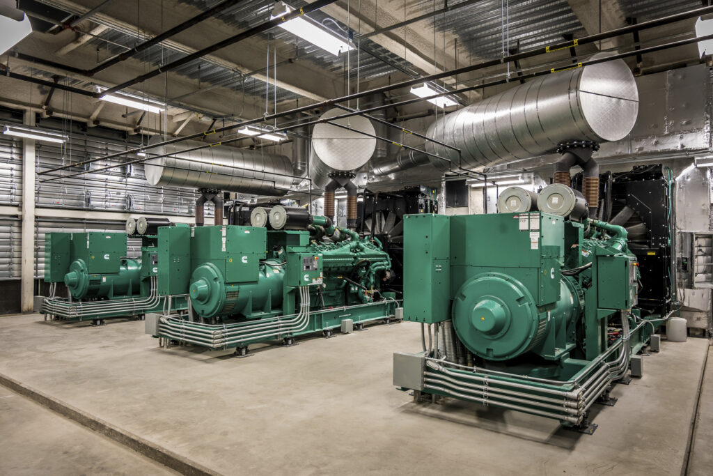
On-site power sources are usually provided in the form of engine-generator sets as, given sufficient fuel supply, they can provide indefinite and reliable runtime. Different facility code requirements will require on-site generators regardless of other mission critical goals; therefore, expanding the system capacity to cover what the NEC would consider “optional standby” (NEC Article 702) is a recommendation. In the implementation of a generator plant for a mission critical facility these are some key recommended best practices:
Provide multiple generators arranged for at least N+1 capacity. Providing at least one redundant unit helps insulate the system from an equipment failure, also allowing for scheduled maintenance and testing to occur without degrading the system capacity. For large systems where the paralleling bus is split, N+2 would be recommended to give a redundant unit on each bus.
On the other end of the spectrum, when considering small systems where a single generator may be sufficient, the design must provide a permanent connection for a temporary generator per NEC Article 700.3(F) to allow for maintenance to occur without interruption to the emergency power supply.
Note that it is not possible to parallel a roll-up generator with one or more permanent gensets; if there is a desire to provide extra capacity in a temporary fashion, the portion of the system that is planned to be supported by the roll-up genset would not be connected to the rest of the emergency power supply system while connected to the temporary unit. This type of arrangement would only be recommended for non-critical equipment needed to stand in the gap during scheduled maintenance.
Segregate the paralleling switchgear bus with one or more tie breakers. Generally, paralleling switchgear consists of a single, contiguous bus connecting two or more gensets and for many applications, this is sufficient.
However, when a given system has many loads required to be restored within 10 seconds or when critical heating, ventilation and air conditioning systems need to be restored as quickly as possible to maintain pressures in hazardous containment areas, the strategy of splitting the paralleling switchgear with a tie breaker allows multiple generators to begin accepting loads prior to achieving synchronization with each other; the tie breaker(s) will be normally open and will close to parallel the generators after loads have transferred.
Generator and paralleling switchgear manufacturers will not guarantee that multiple units will parallel and accept loads within 10 seconds, thus this strategy becomes necessary once the 10-second load demand exceeds the capacity of the smallest genset on the system. Splitting up the paralleling switchgear bus with a tie-tie arrangement similar to the incoming service can help mitigate outages, whether planned or unplanned, on a given bus. (Note: the introduction of tie breakers into a paralleling line-up will preclude “on-board paralleling” offered by some manufacturers.)
Diversify fuel types. The default emergency/standby generator is the diesel generator for two main reasons:
- Their ability to start and come up to rated speed quickly (NFPA 110, Type 10 even for large units), which is code required for NEC Article 700/Article 517 life safety loads.
- The ability to store bulk fuel on-site, which may be a code requirement for certain projects located within seismic zones, although other factors can contribute to this requirement.
However, the runtime for the diesel gensets is limited by the amount of fuel available. The on-site fuel supply is usually sufficient to either ride-through the outage or allow for additional fuel to be delivered, but some past events like Hurricane Sandy, have demonstrated that reliance solely on diesel gensets may not be sufficient in areas with certain risk factors like hurricanes.
Natural gas units have traditionally had limited application for level 1, type 10 systems but for mission critical facilities, a mixed generator plant could bring the benefits of both genset types with the diesel units providing quick response time and guarding against gas supply disruptions while the natural gas units provide indefinite runtime.
As we shift downstream to standby system distribution, if the generator plant is operating at medium voltage, similar strategies for the unit substations should be applied. Downstream of the standby substations or for 480-volt systems, transfer switches and their downstream distribution become the set of next critical components that should be carefully arranged to minimize disruption to any given portion of the system. Recommended strategies include:
Having more, smaller switches is better than fewer, larger ones. For most major distribution components, we can effectively mitigate source outages with double-ended arrangements, but a given transfer switch can become a critical single point of failure as both sources to a given load are supplied by the switch.
It is generally recommended that the facility’s transfer switches complement the mechanical system’s redundancy strategy — each portion of the mechanical system is diversified between two or more transfer switches. For critical and life safety branches within a hospital, the design should consider providing at least two transfer switches per branch even if the load doesn’t seem to warrant it.
Bypass isolation type transfer switches are generally used and recommended to allow bypassing of the transfer switch during maintenance activities, but some critical facilities may want to consider implementing external bypasses for their more critical transfer switches. This strategy allows annual testing to be executed while the switch is fully de-energized and can also alleviate strain that the facility would otherwise experience during transfer switch equipment replacements.
Open transition versus closed transition: Transfer switches are generally provided as either open transition, break-before-make or closed transition, make-before-break and there are benefits and drawbacks to each. Open transition switches are more economical and one could argue, more reliable due to their reduced complexity.
However, loads served by open transition switches will experience a short interruption when returning to normal power, which may be undesirable for certain loads. Conversely, closed transition switches avoid interruption on return to normal power however they are more expensive and require a shut trip strategy to be implemented to ensure that the sources are never paralleled for longer than the rated number of cycles.
Each portion of a system should be evaluated to determine which style is appropriate: if the switch serves an uninterruptible power supply, closed transition would not be needed and some cost can be avoided; if the switch serves lighting in patient areas of a hospital, closed transition may be desired to avoid alarming building occupants.
Selectively coordinate the entire system. Part of designing for unplanned outages includes confining an interruption as locally as possible; the nearest upstream breaker to a fault should be the device to clear the fault. Improper coordination of the trip curves of the breakers or fuses in a system could result in a broader outage than was strictly required to remedy the immediate danger.
Constraining transfer switch capacity not only aids in avoiding “too many eggs in one basket,” this approach also flattens the distribution which will improve selective coordination. While selective coordination is code required for emergency/life safety, legally required standby, COPS, etc., it innately increases the reliability of the entire system if applied broadly.
Additionally, a shallower distribution system will help to avoid the cost of using 30 cycle rated transfers switches.
Distribution design to maximize uptime
When approaching standby and emergency power system design, engineers are designing a system that automatically restores power when it is lost unexpectedly.
However, good design will also consider strategies to mitigate planned outages that a facility may need to impose to execute general maintenance, code required testing or system modifications. Many of the strategies addressed above will inherently help with this but some additional areas that may need careful planning are:
- Site wide distribution of medium voltage circuits. If each unit substation on the site is provided with two different primary circuits, these circuits must be routed such that a shut down on one does not affect the other. This can become a complex analysis when multiple circuits serving many unit substation pass through the same manhole; if a manhole needs to be accessed by personnel, all circuits passing through need to be de-energized without causing an interruption to the system.
- Splitting critical loads between different panelboards, transfer switches and sides of double-ended equipment. Equipment that serves critical processes and mechanical systems should have diversified sources. Sometimes the tendency can be to group like things together — like all chilled water pumps — but a better arrangement would be to have a chiller, one cooling tower, one condenser water pump and one chilled water pump on a given transfer switch and a similar set of equipment on a different transfer switch. Additionally, these switches could be fed from different sides of a double-ended substation. Even if maintenance is required somewhere in the system, at least a portion of the chilled water system will be maintained throughout.