Indirect evaporative cooling allows for space cooling without the addition of moisture. The cooled air never comes in direct contact with the conditioned air, which should help reduce erosion and possible leaks. Consider these codes, standards, and best practices of indirect evaporative cooling.
Learning objectives:
- Understand the evaporative cooling process by comparing and contrasting direct and indirect evaporative cooling.
- Learn about specific applications of indirect evaporative cooling systems.
- Know which standards and guidelines should be considered.
The cooling effect of evaporating water into air is a simplistic, ancient method for building cooling. It is primarily known for having substantial energy savings potential over conventional refrigerant-based cooling for various applications. While this may be true for direct evaporative coolers, indirect evaporative coolers have a wide and growing range of applications.
Evaporative cooling has gained acceptance by the modern HVAC industry. Depending on the application, evaporative cooling can provide one of the simplest methods for cooling over other mechanical refrigeration alternatives while boasting lower energy consumption, no chlorofluorocarbon (CFC) refrigerants, and cost-effectiveness. Though water conservation is of great concern today, evaporative cooling can be appropriately applied to minimize excess water use. Common applications range from comfort cooling in residential and commercial buildings to spot cooling for industrial applications such as mills, foundries, and power plants, and even cooling for highly critical environments such as data centers.
Evaporative cooling works by using the evaporation of water across an airstream to provide the cooling effect, reducing the air’s dry-bulb temperature while increasing its humidity ratio. The air undergoes what is known as an adiabatic saturation process by which the amount of heat removed from the air is equivalent to the heat absorbed by the water as the heat of vaporization. No heat is added to or extracted from the adiabatic process, which follows the line of constant wet-bulb temperature on the psychrometric chart (see Figure 1 for direct cooling). Note that the total enthalpies before and after the adiabatic saturation are the same. The evaporative cooling process is most commonly applied to projects located in dry climates and requiring high air change rates or where operating cost savings can be demonstrated over mechanical refrigeration technologies.
Limitations of evaporative cooling are primarily based on climate conditions, specifically wet-bulb temperature, makeup water consumption, and increased maintenance required to minimize scale accumulation. Water treatment for the prevention of algae and bacteria growth is also an important factor of the design. All of these need to be taken into consideration when specifying an evaporative cooling system. It is important to note that water scarcity in climates ideal for evaporative cooling can often be the limiting factor in the application of this technology.
Direct, indirect evaporative cooling
Direct evaporative cooling (DEC) is the process by which the primary airstream comes in direct contact with the water, either by an extended wetted surface material or with a series of spray nozzles. This direct contact reduces the primary airstream dry-bulb temperature and also increases relative humidity but is limited by the wet-bulb temperature of the entering airstream. Under higher wet-bulb temperatures in humid climates, DEC can be economical for spot cooling in a number of industrial applications or be applied as makeup air for kitchens and laundries. Under lower design wet-bulb temperatures, DEC can be practically applied for comfort cooling. Care must be taken when designing DEC systems to ensure that space relative humidity levels are not compromised.
Indirect evaporative cooling (IEC) combines the benefits of the evaporative cooling effect for sensible cooling without the addition of moisture into the primary air stream. During this process a secondary air source is used to remove heat from the primary air through the use of a heat exchanger. The indirect application has the added benefit of lowering the primary air wet-bulb temperature. The cooling process is similar to cooling with mechanical refrigeration when plotted on a psychrometric chart (see Figure 1). Although indirect evaporative coolers are limited by the effectiveness of the heat exchanger, they can allow for enhanced cooling capability by applying building exhaust or precooled air into the secondary airstream to lower its wet-bulb temperature. This produces lower dry-bulb temperatures that approach the wet-bulb temperature of the secondary airstream. The process can further reduce the leaving air temperature of the primary airstream, improving its range of cooling beyond that of the direct evaporative cooler alone. Latent cooling of the primary airstream can also occur when the secondary air wet-bulb temperature is below the primary air dew point.
IEC and associated technologies are being used on projects globally for many different applications. IEC technology can be divided into two main categories: packaged indirect evaporative air coolers and cooling tower/coil systems.
Packaged indirect evaporative air coolers
The basic packaged IEC unit consists of a primary and secondary air moving device, an evaporative heat exchanger, and a water collection and recirculation system that includes a wetting apparatus and pump. Packaged IEC units may be selected in various configurations of this arrangement with all components in a single-unit casing. Some packaged units are also available with supplemental direct expansion (DX) refrigeration or chilled water coil, a direct evaporative cooling section, and/or heating section. The folded metal or plastic sheet-constructed heat exchanger typically is protected from airborne debris with air filters and may be provided with a corrosive-resistant or moisture-retaining coating. The arrangement of the different sections and components listed above, and the order in which they interact with the primary and secondary airflow, affects the unit’s performance and efficiency under different operating conditions.
A typical packaged IEC unit component arrangement involves placing the IEC heat exchanger upstream of the refrigeration coil in the primary airstream to reduce the coil’s sensible cooling load. The intent of this arrangement is to increase the unit’s overall efficiency during peak load periods. The energy savings is approximately equal to the difference of the energy reduction from the decreased refrigeration load and the increase from the various components. These energy components include IEC water pump, evaporative cooler fan motor, and losses experienced by the primary fan due to the pressure drop across the IEC heat exchanger. The unit efficiency is increased by placing the DX condenser coil in the secondary airstream downstream of the IEC heat exchanger so that the condenser coil is, effectively, direct evaporative cooled. Along with the unit’s efficiency relative to electrical energy consumption, the IEC section’s water consumption rate must also be considered when determining the unit’s overall operating cost.
Packaged IEC units can also be arranged to incorporate heat recovery systems. IEC units that use energy recovery wheels, heat pipes, or run-around coils to precool raw outside air before additional cooling methods will increase the cooling effect by including a DEC section upstream of the heat recovery device to lower the dry-bulb temperature of the exhaust airstream. During any required heating operation, this unit arrangement can operate normally (use the heat recovery device to exchange heat from the hot exhaust airstream to the cold outside airstream) by disabling the DEC section. The DEC section is freeze-protected because it is separated from the outside air during freezing conditions.
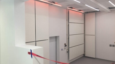
Packaged IEC units can be an attractive option for data center cooling. The energy efficiency of evaporative cooling combined with rapidly advancing data center server technology allows for increasingly higher dry-bulb temperature cold aisles, which contribute to the application of IEC. Figure 2 shows a packaged IEC unit specifically designed for data center cooling applications. This particular unit, also known as a recirculation air conditioning by evaporation (RACE) unit, includes air-to-air evaporative cooling heat exchangers.
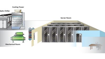
Figure 3 shows a schematic layout of the unit and system components. In general, the unit operates by rejecting heat from the data center hot aisle return air to the atmosphere through the heat exchanger. With low enough ambient temperatures and certain hot and cold aisle design criteria (100 F hot and 70 F cold aisle dry-bulb temperatures are increasingly becoming common), the heat exchanger can reject all of the heat generated by the data center without the added need for evaporative cooling. The heat exchanger is referred to as being “dry” during this mode of operation, and the unit is essentially functioning as an indirect airside economizer.
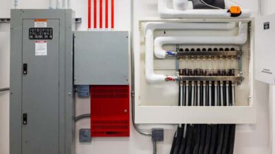
Figure 4 shows a dry air-to-air heat exchanger consisting of watertight polymer tubing through which the primary or recirculated air flows via a supply air fan. The secondary, raw outside air flows around the tubing during dry operation via a scavenger fan. This heat exchanger should operate between 45% and 50% efficiency.
When ambient conditions do not allow for dry operation, the heat exchanger is wetted via the recirculation water system. The water evaporates as secondary air is drawn through the heat exchanger and the primary air is cooled. In this mode, the heat exchanger should be able to cool the hot aisle primary air dry-bulb temperature to within 70% or 80% cooling effectiveness of the secondary air wet-bulb temperature. The primary supply air temperature can be controlled by adjusting the secondary airflow via the scavenger fan variable frequency drive (VFD).
In addition to efficient operation, packaged IEC units with air-to-air heat exchangers benefit data centers by limiting the introduction of outside air pollutants to sensitive and expensive data center equipment during economizer mode periods. A data center cooling unit in economizer mode without indirect heat exchange operation may provide 100% outside air (OA) directly to the space during poor air quality conditions unless controlled otherwise. Indirect systems also do not require barometric relief and will have little effect on space humidity since they operate by sensibly cooling space recirculated air.
Cooling tower/coil systems
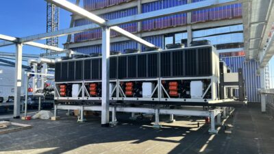
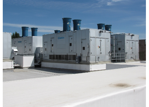
Another common IEC technology is the cooling tower/coil system combination. In this configuration, a cooling tower or other evaporative cooler is combined with a water-to-air heat exchanger coil. This system can have significant benefits because the cooling tower may be located remotely from the cooling coil itself. Cooling tower systems can be ideal for retrofit applications where space may be an issue. Another benefit to this type of IEC is that multiple air-handling units may be piped in various arrangements to a single cooling tower in one centralized location (see Figure 5).
In this method, a cooling tower is used to produce cooled water through an evaporative cooling process. The cooled water is then piped to an air-handling unit (AHU) cooling coil for cooling of the primary airstream. This configuration is a form of IEC by which the primary airstream does not come into direct contact with the water. Typically, this cooled water is used in a precooling coil application where additional downstream cooling methods are required for the design. The introduction of IEC for this type of system can increase capacity and reduce the electrical demand of a DX air conditioner or chiller.
The cooling tower can be selected in a wide variety of configurations to suit the design. Two basic types of evaporative cooling devices can be used: open cooling towers and closed-circuit cooling towers. The open cooling tower is a direct-contact device, which exposes water to the cooling atmosphere. The closed-circuit cooling tower contains an integral closed-circuit heat exchanger with two separate fluid circuits: one exposed to the atmosphere and a primary circuit used to transfer heat from the air-handling unit cooling coil.
Open cooling tower loops tend to collect airborne dirt and impurities that can clog cooling coils and are not recommended for indirect applications. If an open cooling tower system is used, it is recommended that the open and closed loops be separated by a plate and frame heat exchanger. Figure 5 shows a cooling tower installation.
Cooling tower/coil systems vary in size and complexity. One of the more attractive locations for IEC systems is in Las Vegas, mainly due to a considerably low design mean coincident wet-bulb temperature of 66 F. According to local measured bin weather data, the climate is well suited for IEC precool applications for more than 3,200 hours out of the year. In Las Vegas, it is common for casino properties to allow environmental tobacco smoke (ETS) on their gaming floors. The preferred HVAC industry design for spaces with ETS is to exhaust 100% and provide 100% OA as makeup. This consumes a large amount of energy in a climate with a design dry-bulb temperature of 108 F. An IEC cooling tower/coil system installed in a casino property with high OA quantities can offer significant energy savings, reducing plant tonnage and achieving shortened payback periods.
For example, a 50,000-sq-ft casino floor with ETS requires 200,000 cfm of 100% OA based on 4 cfm/sq ft. For a casino operating 24/7, this results in approximately 1,891,000 kWh of electricity to condition the 100% OA using water-cooled centrifugal chillers in a central plant. If a plate and frame heat exchanger is installed on the open-loop cooling tower condenser water system, and the primary side is piped to precool coils installed in each AHU, the energy savings can be evaluated.
The precool coil design reduces the entering 108 F dry-bulb air down to 80 F prior to the chilled water cooling coil, reducing the tonnage on the central plant chillers by approximately 460 tons. Throughout the year, the precool coil operates for approximately 3,200 hours where the ambient air temperature is above 75 to 79 F dry-bulb. The mean coincident wet-bulb temperature is as low as 52 F at 75 to 79 F dry-bulb ambient. For this example it can be demonstrated that the IEC cooling tower/coil system saves approximately 253,000 kWh per year in chiller operation. This equates to approximately $25,000 in annual electricity cost savings versus operating the chillers for the entire load and reduces the mechanical refrigeration load by an average of 130 tons. It should be noted that there is increased water consumption of approximately 780,000 gal per year, which reduces the annual operational cost savings by $1,600 based on the cost of potable water for that region. However, more properties are implementing water saving strategies such as rainwater harvesting and storage to offset cooling tower water consumption. There are several examples of similar IEC cooling tower/ coil systems currently in operation on the Las Vegas Strip.
Standards and guidelines
Several considerations, guidelines, and codes apply to evaporative cooling and associated systems. The most important are operational guidelines intended to minimize Legionella contamination of the makeup water system, such as ASHRAE Guideline 12-2000 – Minimizing the Risk of Legionellosis Associated with Building Water Systems.
Legionella, the bacteria responsible for Legionnaire’s disease, markedly thrives in aquatic environments at temperatures of 77 to 108 F and at conditions containing scale and sediment, biofilms, and stagnation, all or some of which can be present in evaporative cooling systems. ASHRAE 12-2000 includes separate recommendations for direct and indirect evaporative coolers. Indirect evaporative cooling with fluid coolers and cooling towers typically operate at water temperatures ranging of 85 to 95 F, within the range of accelerated Legionellosis growth, and consequently are very likely to contain detectable levels of the bacteria. It is recommended that a water treatment program be provided for this equipment that minimizes the conditions listed above.
An effective water treatment program might include scaling and corrosion inhibitors as well as oxidizing or nonoxidizing biocides approved by the local authority’s environmental regulatory agency (the U.S. Environmental Protection Agency lists these for each state). The selection of these different agents requires knowledge of water chemistry, water microbiology, and characteristics specific to the cooling application; therefore, it is recommended that a qualified water treatment specialist be involved and his or her services used to oversee the treatment. Additionally, quarterly equipment cleaning to reduce the buildup of sediment and debris is recommended to control microbial growth, as well as system draining during shutdown periods to prevent stagnant water conditions.
DEC units using wetted evaporative media operate at water temperatures close to ambient wet-bulb temperature (typically well below 77 F), presenting less risk for accelerated growth of bacteria. It is recommended that the recirculation water be continually bled off or periodically purged at a rate dependent on water quality and airborne contaminant levels to minimize scale and nutrient buildup. Figure 6 is an example of scale buildup on evaporative cooling media that reinforces the importance of water treatment and scale inhibitors. Daily drying of the evaporative media should be applied with dry fan operation (without the recirculating water pump) when possible.
Chemical-free scale inhibitors (electromagnetic) and biocide (electromagnetic as well as ozone-generation) water treatment solutions exist; however, they do not eliminate the need for periodic blow-down nor are they specifically required per the guidelines. Counterintuitively, very pure water from reverse osmosis, deionization processing, or otherwise is not recommended for use with evaporative coolers because of its corrosive nature and decreased ability to wet most types of evaporative media. Given that liquid-to-air heat exchanger water is typically chemically treated or at risk of bacterial contamination, the supply of makeup water (typically potable water) to the IEC unit must be installed in accordance with the International Plumbing Code (IPC) to prevent backflow contamination. Additionally, drain lines and overflow lines required for IEC unit blow-down and excess water must be indirectly connected to an approved disposal location, such as the sanitary sewer system, and not discharged to grade or to a storm sewer.
Related to code restrictions, a potential benefit of IEC units is that they are not directly affected by the various regulations regarding OA intake proximity to building exhaust discharge. As a DEC cooler generally operates by cooling and introducing 100% OA to the building, its intake opening location must be located at least 10 ft horizontally from hazardous or noxious contaminant sources such as vents, streets, alleys, parking lots, and loading docks per the International Mechanical Code (IMC). The effect of contaminated secondary air contact with the IEC heat exchanger should still be considered. Cooling tower discharge itself is considered a contaminated exhaust source and cannot be located proximate to OA intakes.
Is this the right option?
Indirect evaporative cooling is a modern space conditioning approach using a simple form of cooling. It reduces or eliminates the inherent drawbacks of direct evaporative cooling without significantly reducing the well-known energy savings compared to conventional refrigerant-based cooling systems. Where standards, local restrictions, and applicable guidelines do not preclude its use, the potential to supplement or replace refrigerant-based cooling systems in a growing number of applications can translate to considerable cost savings and should be evaluated when designing HVAC cooling systems.
While not specifically discussed in this article, passive forms of indirect evaporative cooling, such as chilled beams, can benefit projects based on similar principles and are worth further discussion and study.
Stephen A. Haines is a senior project engineer at jba consulting engineers. He has been designing indirect evaporative cooling systems in Nevada, Arizona, and California for more than 5 years on various types of gaming, hospitality, health care, and office projects.
James A. Freeman is a senior mechanical designer at jba consulting engineers. He has provided consulting services on large mixed-use hospitality and data center projects in the Southwestern United States and Asia that have incorporated indirect evaporative cooling systems.