Ten common issues that can affect functionality of motors and variable frequency drive (VFD) specification.
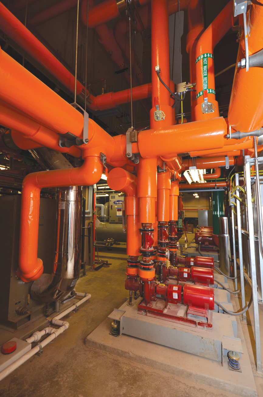
As specifying engineers, we have little control over the applicable efficiency standards and codes that we are mandated to follow. However, we are still entrusted with designing appropriately sized and functional systems. While not an exhaustive list, these are several common motor/variable frequency drive (VFD) issues that can severely affect the functionality of the systems that you specify.
1. A typical motor is rated for a 1.15 service factor. However, many manufacturers state in the fine print for some of their motors that the service factor has to be reduced to 1.0 when the motor is used in conjunction with a VFD. This will kill any overload capabilities that the motor may have and increase the risk of damage when operating under adverse operating conditions (i.e., high ambient operating temperatures). The insulation class of the motor is often a general indication of its overload capability. Class H (125 C rise, heavy duty) insulation is preferred over Class B (80 C rise, general purpose) and Class F (105 C, industrial use).
2. Installing motors in high-altitude locations (typically 3,300 ft above sea level or higher) can also reduce service factor from 1.15 to 1.0 due to reduced cooling air. If you need a specific service factor, spell out the operating conditions under which that service factor should apply.
3. Know what speed range is required by your load. Most general-duty induction motors can only accommodate a 10:1 turndown ratio without overheating their winding insulation. Basic inverter duty rated motors are generally rated for 20:1 turndown when combined with scalar (V/Hz) VFD control methodologies. For many load types, this turndown ratio is more than reasonable. For example, with a fan rated for 10,000 cfm on a design day, does it really make sense to try to control that same fan below 500 cfm? If your load really requires it, depending on the manufacturer, motors rated for use with vector VFD drives can often accommodate 1000:1 or 2000:1 turndown ratios. If you need super-high turndown ratios with high levels of low-speed torque, this will mean using a VFD with vector control. The evolution of VFD design has allowed relatively low-cost VFDs that are capable of both scalar V/Hz and open-loop (sensorless) vector control.
4. Specify closed-loop vector control only if you absolutely, positively know you need it. If you know you need it, you probably already know everything in this article. Closed-loop affords additional precision in speed control compared to open-loop (0.01% versus 0.1%), but requires adding a physical device on the motor to detect rotor shaft rotation (usually an optical shaft encoder or hall effect sensor). However, the shaft encoder can easily add $1000 or more to the cost of a motor and additional wiring. Most common building loads will never need this additional level of precision in control.
5. The sweet spot for peak induction motor efficiency is about 75% load. Efficiency gently rolls off with progressively lower loads. However, below about 20% load, most motors have a dramatic falloff in efficiency due to inconsistent air gap magnetic flux. If you anticipate a significant percentage of your operating hours below that load level, you may want to consider designs that allow you to spread your load among multiple smaller motors. The basic concept is that motors can be staged on only when needed to meet the load requirements. This methodology is taking hold in numerous designs, such as multiple compressor chillers and "fanwall" air handlers.
6. Not all “inverter duty” rated motors are created equal. The high carrier frequency characteristic of VFDs using pulse-width modulation (PWM) with fast switching insulated-gate bipolar transistor (IGBT) inverters can cause a “reflected wave” phenomenon resulting in excessive voltage spikes and circulating currents in the stator windings. These will eventually break down stator winding insulation through overheating and destroy bearing races through electrical discharge machining (EDM). NEMA MG 1 Part 30 provides performance standards for general-purpose motors when used with VFDs, but that does not mean that they are inverter duty rated. MG 1 Part 30 limits peak voltage to 1000 V and dV/dt rise times to 2 msec. A typical VFD using an IBGT inverter on a 480 V distribution can easily exceed these thresholds. When inverter duty motor is required, specify that it should meet the MG 1 Part 31 specifications. Part 31 inverter duty motors have an improved insulation system that can withstand 1600 V peak voltage and a 1 msec rise time along with improved bearing lubrication for higher temperature operation. Optional shaft ground rings can also help mitigate EDM bearing damage by providing a low-impedance path between the stator and rotor.
7. Beware of high VFD output carrier frequencies. High VFD carrier frequencies provide improved PWM output waveform resolution/shaping, which generally results in improved dynamic response and low-speed torque control. However, higher carrier frequencies also exacerbate the “reflected wave” phenomenon. In one manufacturer’s study, an increase in carrier frequency from 3 to 12 kHz reduced insulation life from 100,000 to 25,000 hours. Consult with the manufacturer to determine the minimum acceptable carrier frequency given the control requirements.
8. Whether you have constant torque (positive displacement pumps/compressors) or a variable torque load (fans, centrifugal pumps, etc.) can dramatically affect motor selection. Variable torque loads have a speed-torque relationship that varies with the square of the speed and are much friendlier to motors than constant torque/positive displacement loads. Depending on the specific model of motor and the VFD control methodology, the manufacturer allowed turndown ratio may be dramatically worse with constant torque loads. It may be a 2:1 compared to a 20:1 turndown ratio, which can severely limit the operational speed range for a constant torque load.
9. VFDs can be used not only to slow down a motor, but also to drive it beyond its rated speed (overspeed) by increasing the VFD output frequency above 60 Hz. Some HVAC equipment manufacturers overspeed a motor to allow for fan and motor combinations that really shouldn’t have been allowed in the first place. While I have seen a letter from a motor manufacturer that grudgingly stated that it was probably OK to a certain extent with a particular piece of equipment, recognize that consistent overspeeding of a motor will reduce its useful service life. As the design engineer, you will need to evaluate the load profile with the amount of time expected at the high end of the speed range and determine if there is a cost benefit that offsets the potential reduced reliability. Also note that available motor torque can fall off quickly beyond 60 Hz because you cannot maintain a consistent V/Hz ratio. This is because your drive output voltage cannot exceed your fixed input voltage.
10. Multiple motors may be connected to a single VFD. However, there are some downsides. The chance for motor-drive impedance mismatch is greater, thus increasing the chance of the “reflected wave” phenomenon. All of the motor must be the same size to maintain consistent speed control, and each motor must still be specified with its own overload and short circuit protection per NFPA 70: National Electrical Code (NEC) Article 430.
John Yoon is the senior staff electrical engineer for McGuire Engineers. He has 20 years of experience in the design of electrical distribution systems. His project experience covers a broad spectrum, including high-rise building infrastructure renewal programs, tenant build-outs, mission critical data centers, GMP laboratories, and industrial facilities.
