The end user is ultimately responsible to use the correct code for pressure sensors and transmitters for boiler controls and pressurized vessels.
Pressure sensors and transmitters are extensively used in pressure vessels and boiler systems to monitor fuel, steam, water, and air pressure. These sensors perform safety and control functions within the plant to maintain a safe environment with maximum performance.
Sensors in these applications are typically connected to the process via a threaded connection that allows liquid or gas to be measured in a leak-free condition. To retain the pressure at operating and overload conditions, the pressure port must be able to handle the operating pressure and temperature conditions.
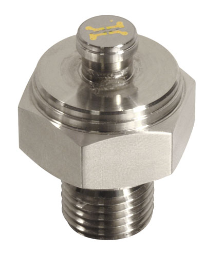
See Figure 1 for a typical pressure sensor with ¼-in. male national pipe thread (NPT) port, a very popular fitting used in boiler tubing and piping systems.
ASME B31 code
The ASME B31 code for pressure piping is a very popular boiler code; it covers power piping, fuel gas piping, process piping, pipeline transportation systems for liquid hydrocarbons and other liquids, and refrigeration piping, as well as heat transfer components and building services piping. Prior to ASME B31, this code was known as ANSI B31.
Within the B31 code are many subcodes that define the exact application and use of pressure sensor fittings and ports that are allowable under the code. The widely used codes include:
- B31.1- Power Piping for industrial plants and marine applications. This code prescribes minimum requirements for the design, materials, fabrication, erection, test, and inspection of power and auxiliary service piping systems for electric generation stations, industrial institutional plants, and central and district heating plants. It also covers boiler external piping for power boilers and high-temperature and high-pressure water boilers in which steam or vapor is generated at a pressure of more than 15 psig.
- B31.3 – Process Piping for use in chemical & petroleum plants, refineries processing chemicals and hydrocarbons, water and steam. The code contains rules for piping found in petroleum refineries; chemical, pharmaceutical, textile, paper, semiconductor, and cryogenic plants; and related processing plants and terminals. The code covers requirements for materials and components, design, fabrication, assembly, erection, examination, inspection, and testing of piping handling fluids, gases, steam, and air. Pressure sensors with either male or female process ports are covered under this code whenever the pressure is more than 15 psig.
Pressure port design considerations under B31.3
The B31.3 code is intended for manufacturers, users, constructors, designers, and others concerned with the design, fabrication, assembly, erection, examination, inspection, and testing of piping, plus all other potential governing entities.
All pressure sensors employ some form of a diaphragm that is either machined from one piece of metal or welded or O-ring clamped as a two-piece assembly. This section of the pressure sensor is the thinnest and most sensitive of all components.
Figure 2(a) shows a one-piece thick 0.022-in. diaphragm while Figure 2(b) depicts a welded thin 0.001-in. thick diaphragm. Together, with the thickness and the type of metal, the operating pressure and operating temperature range dictate the safety conditions under which the pressure sensor can operate.
Stresses and quality factors (for welded diaphragms only) are other important design considerations taken into account under B31. Metals such as strain hardened A-479-316L stainless steel level 2 need to be impact tested when used below -20 F. The impact tests must conform to B31.3 Table 323.2.2.
When sensors are constructed from metals such as N07718 (Inconel 718) and N10276 (Hastelloy C276) that offer temperature resistance from -325 F to +300 F, no impact testing is required.
Based on the calculations and thermal limits for the metals as required by B31.3 code, below are samples of calculations needed to determine the correct diaphragm thickness for a one-piece pressure sensor designed free of welds. Each sensor material has different containment capabilities based on the material properties and exposure to temperature.
A-479 316L stainless steel
Pressure limited by thread shear strength
Assuming the female thread material is at least as strong as the filling, the shear area of threads at the pitch line (tight) is: Ashear: = π ÷ 2 • (E0 + E1) • Leff ÷ 2 = 0.3in2
Cross-section area on which pressure acts (use pipe OD for conservatism): Ashear: = π ÷ 2 • (E0 + E1) • Leff ÷ 2 = 0.3in2
If the allowable shear stress is 0.6*S, then the allowable pressure limited by the fitting thread strength is: Ptd: = 0.6 • A shear • S1 ÷ Ap = 13136 psi
Thread allowable test pressure at yield: 0.6 • A shear • S1.tst ÷ Ap = 58994 psi
Closure (membrane) calculations: Paragraph 304.4.1
Table 304.1.1 specifies the use of ASME Section VII, Div 1 Paragraph UG-34 for the calculation of the thickness of a flat closure. The 2010 Edition, 2011a Addenda is used for these calculations.
Assuming the head to shell joint is equivalent to Fig UG-34(h): Ch: = 0.33
Part number
Membrane thickness tolerance: Tol: = 0.001 • in
Membrane nominal thickness: tm.noma: = 0.008 • in
Minimum thickness: tma: = tm.noma – Tol – ca = 0.007 in
Membrane maximum allowable pressure: Pma: = S1 • Es • tma2 ÷ Ch • Di2 = 25.8 psi
Maximum allowable working pressure: Pa: = min (Ps, Ptd, Pma) = 25.8 psi
Use a maximum allowable working pressure of: MAWPa: = 25 psi at temp = 300 °F
Membrane allowable test pressure at yield: Pma.tst: = S1.tst • Es • Tma2 ÷ Ch • Di2 = 116 psi
Maximum test pressure: Pa.tst.max:= min (P1.tst.A, Ptd.tst, Pma.tst, 1.5 • Rr1 • Pa) = 38.7 psi
Minimum test pressure: Pa.tst.min:= min (Pa.tst.max, 1.5 • Rr1 • MAWPa) = 37.5 psi
N07718 Inconel 718
Pressure limited by thread shear strength
Assuming the female thread material is at least as strong as the filling, the shear area of threads at the pitch line (tight) is: Ashear: = π ÷ 2 • (E0 + E1) • Leff ÷ 2 = 0.3in2
Cross-section area on which pressure acts (use pipe OD for conservatism): Ap: = π ÷ 4 • Dp2 = 0.229in2
If the allowable shear stress is 0.6*S, then the allowable pressure limited by the fitting thread strength is: Ptd: = 0.6 • A shear • S3 ÷ Ap = 27722 psi
Thread allowable test pressure at yield: Ptd.test: = 0.6 • Ashear • S3.tst ÷ Ap = 118077 psi
Closure (membrane) calculations: Paragraph 304.4.1
Table 304.1.1 specifies the use of ASME Section VII, Div 1 Paragraph UG-34 for the calculation of the thickness of a flat closure. The 2010 Edition, 2011a Addenda is used for these calculations.
Assuming the head to shell joint is equivalent to Fig UG-34(h): Ch: = 0.33
Part number
Membrane thickness tolerance: Tol: = 0.001 • in
Membrane nominal thickness: tm.noma: = 0.008 • in
Minimum thickness: tma: = tm.noma – Tol – ca = 0.007 in
Membrane maximum allowable pressure: Pma: = S3 * Es • tma2 ÷ Ch • Di2 = 51.1 psi
Maximum allowable working pressure: Pa: = min (Ps, Ptd, Pma) = 51.1 psi
Use a maximum allowable working pressure of: MAWPa: = 50 psi at Temp = 300 °F
Membrane allowable test pressure at yield: Pma.tst: = S3.tst • Es • Tma2 ÷ Ch • Di2 = 218 psi
Maximum test pressure: Pa.tst.max:= min (P3.tst.A, Ptd.tst, Pma.tst, 1.5 • Rr3 • Pa) = 80.4 psi
Minimum test pressure: Pa.tst.min:= min (Pa.tst.max, 1.5 • Rr3 • MAWPa) = 78.7 psi
N10276 Hastelloy C276
Pressure limited by thread shear strength
Assuming the female thread material is at least as strong as the filling, the shear area of threads at the pitch line (tight) is: Ashear: = π ÷ 2 • (E0 + E1) • Leff ÷ 2 = 0.3 in2
Cross-section area on which pressure acts (use pipe OD for conservatism): Ap: = π ÷ 4 • Dp2 = 0.229in2
If the allowable shear stress is 0.6*S, then the allowable pressure limited by the fitting thread strength is: Ptd: = 0.6 • Ashear • S2 ÷ Ap = 19665 psi
Thread allowable test pressure at yield: Ptd.tst: = 0.6 • Ashear • S2.tst ÷ Ap = 32250 psi
Closure (membrane) calculations: Paragraph 304.4.1
Table 304.1.1 specifies the use of ASME Section VII, Div 1 Paragraph UG-34 for the calculation of the thickness of a flat closure. The 2010 Edition, 2011a Addenda is used for these calculations.
Assuming the head to shell joint is equivalent to Fig UG-34(h): Ch: = 0.33
Part number
Membrane thickness tolerance: Tol: = 0.001 • in
Membrane nominal thickness: tm.noma: = 0.008 • in
Minimum thickness: tma: = tm.noma – Tol – ca = 0.007 in
Membrane maximum allowable pressure: Pma: = S2 • Es • tma2 ÷ Ch • Di2 = 38.6 psi
Maximum allowable working pressure: Pa: = min (Ps, Ptd, Pma) = 38.6 psi
Use a maximum allowable working pressure of: MAWPa: = 35 • psi at temp = 300 °F
Membrane allowable test pressure at yield: P ma.tst: = S2.tst • Es • Tma2 ÷ Ch • Di2 = 63 psi
Maximum test pressure: Pa.tst.max:= min (P2.tst.A, Ptd.tst, Pma.tst, 1.5 • Rr2 • Pa) = 57.9 psi
Minimum test pressure: Pa.tst.min:= min (Pa.tst.max, 1.5 • Rr2 • MAWPa) = 52.5 psi
Codes B31.3 versus B40.2
While B31.3 specifically defines the design of fittings and tubing for pressure vessels and boilers, the codes B40.1 and B40.2 are used for analog dial gauges and flange design, respectively. These two codes should not be confused since they serve different roles. Many pressure sensor manufacturers use the B40.2 code for pressure sensors when employing process ports such as 1/4-in. NPT, ½-in. NPT, or F250C. This is a misapplication of the code as it does not take into account diaphragm thickness and metals as required by B31.3. The B40 codes are primarily focused on analog devices and flanges, which does not calculate the minimum diaphragm thickness or limit materials to ensure containment under overload conditions.
The end user is ultimately responsible to use the correct code for pressure sensors and transmitters for boiler controls and pressurized vessels. Failure to comply with code could lead to expensive failures, fines, shutdowns, and unnecessary safety hazards. The end users, particularly in Canada, must check with their pressure sensor suppliers for CRN listings under code B31.3 when specifying pressure sensors in process plants, power plants, boiler controls, and many other critical applications.
Karmjit Sidhu is VP of business development for American Sensor Technologies where he spearheads sales and marketing and also focuses his efforts on the conceptual design of new products.