Engineers can create a balanced approach to the energy and indoor air quality (IAQ) trade-off with dedicated outdoor air systems that fit the needs of the facility and its inhabitants.
As engineers, we are often challenged with improving IAQ issues to ensure occupant safety and comfort. Whether the functions of the building are to heal patients, learn new healthcare practices, or conduct experiments in an organic chemistry class, air quality is crucial to maintaining a healthy environment. While maintaining these environments we are faced with a give-and-take situation. We need the IAQ to be at the highest quality, but we are also striving to maintain construction and operation costs of the facility. Engineers and design teams have made great strides in creating a balanced approach to the energy and IAQ trade-off with dedicated outdoor air systems that fit the needs of the facility and its inhabitants.
Dedicated outdoor air systems
At the heart of a dedicated outdoor air system (DOAS) is a method of supplying outside air directly to the room or to the return air intake of the space fan coil unit. Beyond that basic distinction, there are several choices on how to configure your DOAS that will have an impact on the energy savings and installation cost of the system. If you have high-occupant density spaces, how will the system integrate with the demand controlled ventilation (DCV) required by ASHRAE 90.1 and the International Energy Conservation Code (IECC), which is the basis of most state energy codes in the U.S.? How will the dedicated outdoor air unit cool, heat, and dehumidify the outside air delivered to the space in a way that reduces energy costs and maintains occupant comfort? These are all questions an engineer must pose to himself and colleagues to ensure the best solutions are identified for the project. While keeping installation and operational costs low is a goal in most projects, it should not be at the expense of occupant comfort or safety.
First, consider whether the DOAS delivers air directly to the space, parallel to the fan coil unit, or if it is sent to the fan coil unit return in series with the fan coil unit. A parallel DOAS is usually supplied at a relatively neutral temperature compared to the room temperature to maintain the comfort of the people in the space and avoid cold drafts. Typically the temperature of this air would be delivered between 68 and 75 F and be dehumidified to 50% relative humidity (RH) or less. In addition, the fan coil unit usually does not have a large enough coil capacity to dehumidify the air. In most climates, it is essential that the outside air unit can dehumidify by cooling the outside air to 55 F or less. With parallel DOAS, the outside air unit needs to reheat the outside air to 68 F after it is dehumidified. This presents the potential for energy waste because all spaces connected to the dedicated outside air unit will receive the same supply air. As a result, rooms and fan coil units that are in cooling will be chilling the air that has just been heated. This cooling is an energy waste.
This energy is conserved when outside air is delivered to the return air of a Series DOAS fan coil unit. With this system, the dedicated outdoor air unit will cool and dehumidify the air as much as needed to supply 55 to 75 F air that is 50% RH or less. This can be accomplished by measuring dew point temperature upstream of the cooling coil and cooling the air as necessary to reduce dew point temperature to 55 F or less. With this approach, the engineer must be careful to size the fan coil unit based on 100% return air. This will ensure that the fan coil unit is large enough to condition the space load if the outside air is reduced or is supplied at 75 F dry-bulb temperature.
A drawback of the Series DOAS approach is that the fan coil unit needs to run continuously during occupied mode in order for outside air to be delivered from the return air of the unit to the breathing zone of the space as required by ASHRAE 62.1. A fan coil unit with a variable speed fan can reduce this cost. Conversely, with a parallel DOAS, the fan coil unit only needs to run when the thermostat calls for sensible heating or cooling. Deciding which type of DOAS to use is specific to the building and requires detailed energy analysis during system selection to determine the best fit for the building with the lowest life cycle cost.
Recovering and saving energy
Dedicated outdoor air units provide an excellent means for utilizing exhaust air energy recovery devices. Sensible and latent transfer devices, such as total energy recovery wheels, offer the most potential for energy recovery, but there is also the potential for cross contamination from exhaust air to outside air. The cross contamination should also be considered as a deterrent to the quality of the outside air supplied to the space and will require more outside air delivery. Instead, when working in lab spaces, sensible heat recovery devices are used like a glycol runaround loop from a coil in the exhaust to a coil in the outside air.
The dedicated outdoor air unit ensures that humidity is not supplied into the building by the mechanical system in parallel or series DOAS. It is best to have a cooling coil downstream of the energy recovery device to further cool and dehumidify the outside air to a discharge dew point that will keep space humidity low. Air must be dehumidified even when it is supplied to the fan coil unit for further processing, as is the case with a Series DOAS. This fan coil unit may not be calling for cooling because space temperature is satisfied. If the outside air is not dehumidified, the humid air outside will be delivered to the building, causing high humidity problems such as mold and mildew.
Another means of saving energy and costs associated with dedicated outdoor air units can come from using modulating dampers or variable air volume (VAV) boxes on the outside air supply duct with a variable frequency drive (VFD) on the supply and exhaust fans. Carbon dioxide or occupancy sensors can be used to modulate the dampers controlling the amount of outside airflow to each zone. The VFD will modulate the supply fan based on duct static pressure. This allows the system to use a smaller dedicated outdoor air unit and smaller ductwork because they can be sized with diversity in mind rather than using a constant volume unit. This can often be a significant size difference, which could lead to costs savings for the client. In addition, the reduction in the amount of outside air processed is a significant energy savings.
Health sciences building case study
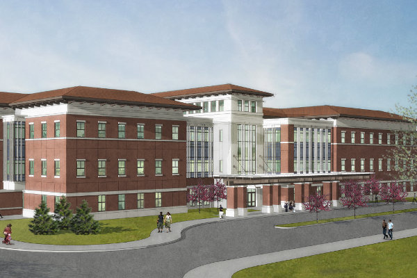
The Michael A. Evans Center for Health Sciences is a four-story (including basement), 140,000-sq-ft new building on the southeast corner of the Marian University campus located in Indianapolis. The building will house the College of Osteopathic Medicine and the university’s School of Nursing, so doctors and nurses can train together. The building will feature two large lecture rooms, five general classrooms, one computer lab, three skills labs, one anatomy lab, one osteopathic manipulative medicine lab, six simulation rooms, 10 teaching clinic exam rooms, and a small meditation chapel. The building was designed to LEED Gold standards and is currently under review by the U.S. Green Building Council.
The Marian project presents a good example of a parallel DOAS and some of the benefits associated with using this type of system. The project uses a dedicated outdoor air unit coupled with a water-cooled variable refrigerant flow (VRF) system. Since the building was designed around interprofessional training and experimental learning, it allowed us the opportunity to implement outdoor air systems that would mirror the healthcare environments the students would be working in after graduation. Dedicated outdoor air units are required with VRF in this climate zone due to high humidity in the summer and cold winters. The VRF units do not have the capacity to treat the outside air without some pretreatment. The high airflow requirements in the anatomy lab require air that is conditioned and ventilated with its own 100% outside air unit and is not part of the VRF system.
Layout and location of the dedicated outdoor air unit
The dedicated outdoor air unit is an energy recovery air handler in the basement mechanical room. Outside air and exhaust air are ducted to separate areaways. The unit has a four-angstrom molecular sieve total energy recovery wheel, water source heat pump (WSHP), cooling and heating coils, and a hot gas reheat coil. The WSHP condensing unit is on the same system with the VRF condensing units, so heat from the interior zones can be used for heating the outside air and vice versa. The hot gas reheat coil takes the hot gas from the evaporator coil and uses it for reheating. The unit dehumidifies and heats the air to supply neutral air directly to the rooms via ductwork from the air handler to each room in the building. The unit has a VFD on the supply fan and the exhaust fan. All high-occupant-density rooms have carbon dioxide sensors and motorized dampers for a DCV system to ensure the (IAQ) levels are safe for users. The motorized damper opens and closes to control the amount of outside air to each room based on the carbon dioxide reading and its setpoint. The supply fan VFD varies the speed of the supply fan based on the static pressure in the duct as measured on each floor. Exhaust air tracks the supply fans’ speed to maintain positive building pressure. Airflow measuring stations and dampers in the exhaust ductwork maintain flow to restrooms, maintenance closets, and other spaces with code-required exhaust.
VRF fan coils are primarily horizontal ducted types located above the ceiling with small offices using cassette units mounted in the ceiling. Since outside air is ducted directly to each space for a parallel DOAS, the VRF fan coils vary their fan speed and shut down as required to satisfy the space load. Some of the VRF manufacturers were not comfortable with series DOAS because high outside air to some spaces required overriding of the VRF to a higher CFM setting. Some manufacturers did not like the possibility of a high percentage of outside air potentially at 55 F in the return air that goes to the unit.
Limiting energy waste
To limit energy waste from recooling or reheating of outside air by the fan coil units, the supply air from the dedicated outside air unit is reset from 60 to 70 F in a linear relationship based on the condenser water loop supply temperature. If the condenser water supply temperature is at 80 F or higher, the supply air shall be 60 F. If the condenser water supply temperature is at 60 F or lower, the supply temperature shall be 70 F. Outside air temperature is typically used to reset the schedule, however, because if the building has a high internal load with people, laptops, and desktop computers, it makes more sense to vary the supply air based on the condenser water temperature, which will track the average load of the building more closely. The condenser water loop supply temperature is allowed to vary from 60 to 90 F by the system boilers and cooling towers.
Another method used at the Evans Center to limit recooling or reheating of outside air is to cool or heat the air only as much as needed to reach the current supply air setpoint. The temperature and humidity sensors in the outside air downstream of the energy recovery wheel measure the dew point of the air. When the dew point is equal to or greater than 55 F, the dedicated outside air unit will enter dehumidification mode and override the cooling coil to supply 52 F dry bulb downstream of the cooling coil. Modulating hot gas reheat in the unit is turned on to maintain the current supply air setpoint.
The Evans Center is pursuing LEED Gold, and an energy analysis was performed using Trace 700 comparing the proposed system to the LEED baseline from ASHRAE 90.1-2007 Appendix G, which is system 5: Packaged rooftop VAV with reheat with direct expansion cooling and natural gas boiler. The cumulative results of these energy-conserving features and savings from energy-efficient lighting at the Evans Center resulted in an energy savings of 43% and a cost savings of 36% versus the baseline system. This allows us to pursue 12 points under Energy and Atmosphere credit 1: Optimize Energy Performance. The savings in energy for just the HVAC components is 65%.
Conclusion
These examples illustrate the capabilities and functions of a dedicated outdoor air system used in two successful projects. As engineers, we are continuously striving to identify new trends and methods to improve outcomes for our clients. Using a dedicated outdoor air system is a means of achieving space comfort and IAQ requirements while balancing construction costs and lowering operational costs to provide clients with a long list of benefits.
Kussow PE, LEED BD+C, is a Design Engineer at BSA LifeStructures. He has 18 years of experience working extensively with projects pertaining to energy savings in the built environment with an emphasis on discovering innovative ways to save energy and costs through HVAC systems.
Cooling on campus
Another example of a project that applies principles of best practice with dedicated outdoor air systems is Purdue University’s Health and Human Sciences Building located on the Purdue campus in West Lafayette, Ind. This building is a 127,300-sq-ft facility consisting of three floors and a basement. The facility will be constructed to combine the departments of Speech Language and Hearing Sciences, Clinical Facilities, and Medical Education (IU School of Medicine–Lafayette). The building consists of offices, classrooms, a biosafety level two lab, exam rooms, and a pathology lab.
This project is a hybrid system using two dedicated outside air systems to supply outside air to zones served by fan coil units, chilled beams, and VAV boxes with reheat. The majority of the lab, classroom, exam, and office spaces are served by chilled beams. However, fan coil units are used to supply high latent heat gain areas such as large conference rooms and entrances to the building. The VAV boxes with reheat are used for spaces with high minimum airflow requirements, such as restrooms and some labs. The dedicated outside air units have four angstrom molecular sieve total energy recovery wheels, steam preheat coils, and chilled water coils with UV lights upstream of the supply fan, while downstream of the supply fan is a steam humidifier. Air from the dedicated outside air units is supplied to airflow control valves and then sent to four-pipe chilled beams. In fan coil unit zones the dedicated outside air unit supplies air to VAV boxes with reheat coils ducted directly to the spaces. Fan coil units are independent from the outside air.
The dedicated outside air unit chilled water coil discharge temperature is set at 52 F dry bulb. This low discharge temperature is necessary to dehumidify the building to ensure there are no condensation issues with the chilled beams. This is a Series DOAS where the dedicated outdoor air unit supplies air to the return connection of the fan coil units and to the chilled beams, not directly to the space. The choice of active chilled beam forces this direction since the air supplied to the chilled beam is used to induce more airflow into the space. The benefit of the chilled beam is that no fan energy is used at the room level. Demand control ventilation with carbon dioxide sensors or occupancy sensors are used to adjust the supply of outside air to fan coil units and chilled beams. The dedicated outdoor air unit supply fan VFD varies based on supply duct static pressure, and the exhaust fan VFD tracks the supply fan to maintain the building’s positive pressure.
Chilled beams for labs
In the labs, chilled beams were only used on high sensible load rooms where the calculated cooling airflow is greater than the minimum six air changes per hour required for the lab. In these labs, the chilled beams are used to lower the airflow requirement closer to the minimum standard. In labs where the airflow was already at the minimum level of air changes required, airflow control valves with reheat coils were used. In some cases a supply airflow control valve with the duct heating coil would be placed in the same lab with a supply airflow control valve serving a chilled beam. Airflow is increased in both, as required to satisfy space temperature. If airflow is at maximum and additional cooling is required, then the chilled beam cooling turns on. At minimum airflow when heating is required, the duct coil and chilled beam heating coil are turned on to satisfy the space temperature.
Energy analysis using Trace 700 showed this system using 26% less energy than the baseline system from Appendix G of ASHRAE 90.1-2007 using system 5: Packaged VAV with Reheat and DX cooling. The overall savings is a result of large savings in space heating and fan energy that makes up for some increase in pumping and cooling energy. The savings in reheat and fan energy is a direct result of 58% less outside air with the hybrid chilled beam system than with the Appendix G baseline system.