This explains how to size motor circuit conductors, determine circuit breaker ratings and disconnecting means at a well station.
Sizing the circuitry for low-voltage motors at a well station used NFPA 70: National Electrical Code (NEC) Article 430.250, which illustrates the full-load current (FLC) for three-phase alternating current motors, including both induction-type squirrel cage motors and wound-rotor motors.
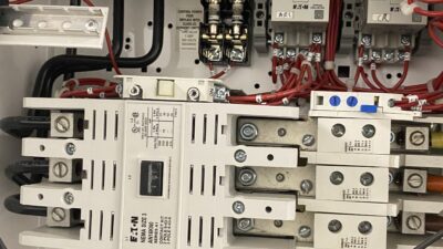
The disconnecting means throughout the case study will assume that the short circuit interrupting capacity needed is less than 10 kiloampere interrupting capacity (kAIC). kAIC is the maximum short-circuit current that an electrical protective device can safely interrupt without failing. This ensures electrical protection devices are properly rated to handle potential fault currents and prevent equipment damage. The disconnecting means mentioned in the following will detail the sizing of a nonfusible disconnect switch with a 10 kAIC rating. Manufacturers only provide heavy-duty disconnect switches in the following sizes: 30, 60, 100, 200 and 400 amperes (A). There are other acceptable disconnecting means that could be used.
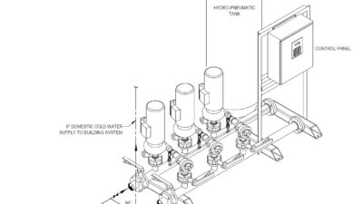
A well station is used in both municipal and private water systems to extract groundwater from underground aquifers and deliver it into a water distribution system. These stations are essential because they maintain a consistent, pressurized supply of clean water. Access to clean and safe water is crucial for everyone. Typically, well stations are outdoors near the water source and in areas that are easily accessible for maintenance personnel.
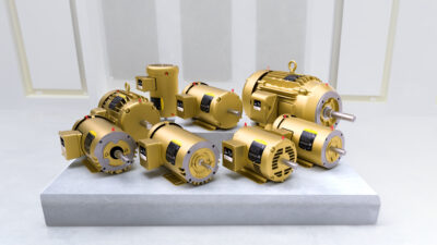
Common equipment at a well station includes well pumps, exhaust fans and various miscellaneous loads such as lighting, electrical receptacles and instrumentation devices. It is the responsibility of process mechanical engineers to determine the motor horsepower (hp) and voltage required based on the expected gallons per minute needed at the well station and the type of motor drive used.
Some possible motor drives could be a variable frequency drive (VFD), reduced voltage soft starter (RVSS) or full-voltage nonreversing (FNVR). Once determined, the process mechanical engineers provide electrical engineers with the process equipment information (see Table 1).

For VFDs, a circuit breaker would be used, but for RVSS and FVNR drives, a motor circuit protector would be used. For the motor circuit conductors, copper, THWN insulated cables will be used. The conduit and grounds were not included as they are not the focus of this case study.
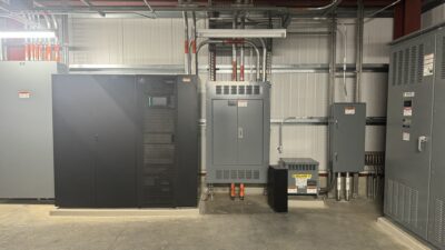
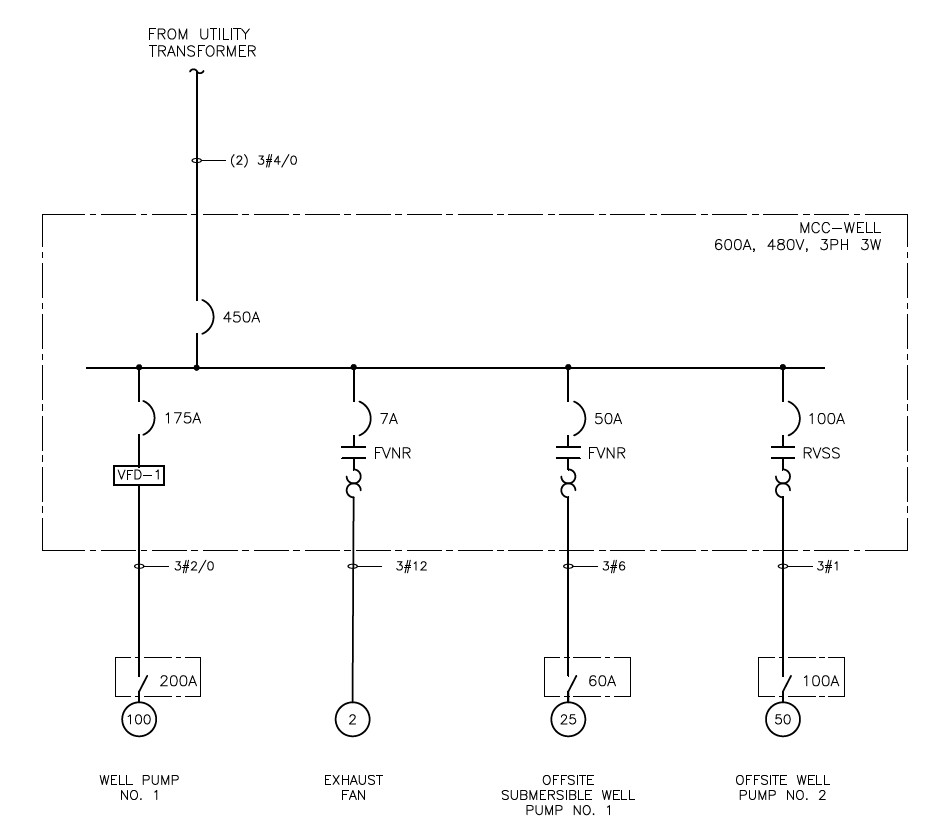
It is assumed that the well station operates solely on utility power without the need for backup power. The well station is powered by a utility transformer that supplies a motor control center (MCC) designated as MCC-Well. This MCC includes four motor loads: a 100 hp well pump, a 2 hp exhaust fan, a 25 hp off-site submersible well pump and a 50 hp off-site well pump. All these motors are 480 (volts) V, three-phase induction-type squirrel cage and wound-rotor motors.
To determine the FLC for each motor, Table 430.250 must be used. Table 2 includes the FLC values from NEC Table 430.250 and information from the process mechanical engineer. This table is used throughout the case study to ensure compliance with NEC.
Main service at the well station
The main service is powered by a utility transformer that supplies MCC-Well. To size the main service conductor and the main circuit breaker, all four motors must be considered. Referring to Part II, motor circuit conductors, the motor conductors must be rated for 125% of the FLC of well pump No. 1 added with the combined FLCs of the other three motors connected to the system. The motors nameplate FLA of offsite submersible well pump No. 1 is larger than the NEC FLC, so 36 A must be used in the calculation.
Referring to Table 2, the total FLC, excluding well pump No. 1, is 104.4 A. For well pump No. 1, calculate 125% of its 124 A rating, which equals 155 A. When adding 104.4 A and 155 A together, the total is 259.4 A. It was decided to use a 450 A main circuit breaker to accommodate the connected load and future expansion. In accordance with Table 310.16 of the NEC, the appropriate conductor size is two sets of three #4/0.
Well station pump No. 1
Well pump No. 1 is a 100 hp, 480 V variable speed motor on a VFD. Referring to Table 2, the FLC of this motor is 124 A. The motor circuit conductors must be capable of handling 125% of the FLC, which is 155 A. The standard breaker size to use in this case per NEC Table 240.6(A) is 175 ampere trip. In accordance with Table 310.16 of the NEC, the appropriate conductor size is three #2/0. Because this well pump is not located within sight of the MCC, the disconnecting means must be positioned at the motor location.When sizing the disconnecting means, the rating must be no less than 115% of the motor’s FLC. This would require a disconnect switch rated for 142.6 A. The smallest standard disconnect switch size to comply is 200 A.
Exhaust fan No. 1
Exhaust fan No. 1 is a 2 hp, 480 V constant speed motor. Referring to Table 2, the FLC of this motor is 3.4 A. The motor circuit conductors must be capable of handling 125% of the FLC, which is 4.25 A. The standard motor circuit protector size to use in this case per NEC Table 240.6(A) is 7 AT. In accordance with Table 310.16 of the NEC, the appropriate conductor size is three #12. Because this exhaust fan is located within sight of the MCC, the circuit breaker within the MCC can be used as the motor disconnecting means.
Off-Site Submersible Well Pump No. 1
Off-site submersible well pump No. 1 is a 25 hp, 480 V constant speed motor. Referring to Table 2, the FLC of this motor is 34 A, but the nameplate FLA is 36 A. The motor circuit conductors must be capable of handling 125% of the FLA, because it is larger than the NEC FLC. In this example, 125% of the FLA is 45 A. The standard motor circuit protector size to use in this case per NEC Table 240.6(A) is 50AT.
In accordance with Table 310.16 of the NEC, the appropriate conductor size is three #6. Because this well pump is not located within sight of the MCC, the disconnecting means must be positioned at the motor location.When sizing the disconnecting means, the rating must be no less than 115% of the motor’s FLC. This would require a disconnect switch rated for 41.4 A. The smallest standard disconnect switch size to comply is 60 A.
Off-site well station pump No. 2
Off-site well pump No. 2 is a 50 hp, 480 V constant speed motor on a RVSS. Referring to Table 2, the FLC of this motor is 65 A. The motor circuit conductors must be capable of handling 125% of the FLC, which is 81.25 A. The standard motor circuit protector size to use in this case per NEC Table 240.6(A) is 100 AT. In accordance with Table 310.16 of the NEC, the appropriate conductor size is three #1. Because this well pump is not located within sight of the MCC, the disconnecting means must be positioned at the motor location. When sizing the disconnecting means, the rating must be no less than 115% of the motor’s FLC. This would require a disconnect switch rated for 74.75 A. The smallest standard disconnect switch size to comply is 100 A (see Figure 4).