Two different heating systems show how different the design and specifications can be
The following shows the range of sizes hydronic heating systems can span. One is a relatively small hydronic heating plant in an elementary school annex and the other is one of the largest heating plants in a massive district heating plant at O’Hare International Airport in Chicago.
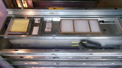
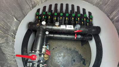
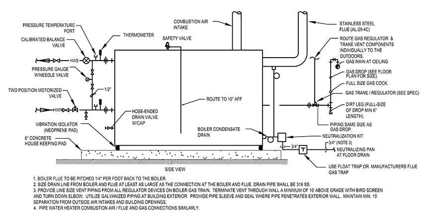
The school project includes two 500 MBH (input) gas-fired, condensing water–tube boilers (see Figures 1 and 2). The system operates at 150 F supply and 120 F return water temperature. It is a variable primary flow system primarily serving perimeter hydronic terminal heating equipment including cabinet heaters, fin-tube radiators and radiant heating panels (Figure 3).
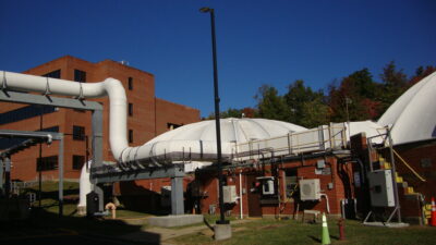
In contrast, the O’Hare International Airport heating plant consists of eight 75,000 MBH water-tube high–temperature water HTW boilers split into two fully redundant plants delivering 410 F water at 400 PSIG operating pressure. While most systems operating at this temperature are high–pressure steam plants, the airport operates their system under high pressure to maintain a high–temperature water system.
Heat exchangers at each terminal develop conventional 180 F water for air handling units and terminal devices in a decoupled tertiary loop. The plant is currently in the construction process of replacing all eight existing boilers with new, higher efficiency, lower NOX–emitting water–tube boilers.