This reviews the types and configurations needed to specify modern lighting controls

Learning Objectives
- Understand the types and configurations of networked lighting controls.
- Learn options for specifying modern lighting control systems.
- Explore nomenclature and labeling options for lighting controls.
The lighting control industry has been evolving faster than the engineering or design industry can keep up with. Despite the evolution of lighting controls, the way lighting control systems are shown seem to have changed very little. Networked controls and programmable, addressable light fixtures and button stations have been replacing traditional toggle switches for the past decade; however, many designs still use traditional symbols and specifications have traditional switches.
Anyone who has been in the design or construction field for more than 10 years is very familiar with the traditional toggle switch form of lighting controls. These components switch line voltage, typically 120-volt or 277-volt in the U.S. When more than one switch location is needed, three- or four-way switches are used with “traveler” conductors between each switch.
While this configuration has worked well for nearly a century, it requires a substantial amount of line voltage wiring. When controls need to removed or added, changes are fairly inflexible on how they need to be wired. Lighting relay systems have been used for more than 70 years and these systems can use low voltage (which NFPA 70: National Electrical Code classifies as 50 volts or less) to control groups of relays. Adding control points can be fairly easy, given the ability to use low-voltage cabling, but adding circuits can be costly depending on the capacity of the relay panel and distance to the space served for line voltage wiring in raceway.
Relay or motorized component panels have been evolving to include programmable features and network capability, and these systems are well-suited for large areas such as conference centers, manufacturing or industrial spaces. When the panels are co-located with the electrical distribution serving the loads, the additional wiring cost can be minimized. The primary disadvantage of these systems is the cost and complexity of changing zoning or moving luminaires to alternate zones can be high, depending on the arrangement.

Lighting controls
Electrical design drawings have several traditional ways of showing lighting controls, which have been consistently typical over the past decade. Modern lighting controls have adapted to account for technology that can now be integrated into lighting fixtures. Luminaire control options have expanded over the past decades to include:
- Occupancy or vacancy sensing.
- Daylight sensing and control.
- Addressable networking for programmable assignment.
- Wireless controls using Bluetooth, ZigBee or Wi-Fi topologies.
- Time-of-day scheduling.
- Tunable white or RGBW control.
Lighting controls have evolved in response to wireless and addressable lighting fixtures. Programming lighting controls can be done over wired low-voltage, such as CAT-5E cabling or with wireless communication protocols. The obvious advantage with these controls is that the traditional line voltage control wiring of old is no longer needed at each control point and the programming flexibility allows for adjustments to occur at any time without the need to rewire the system when each luminaire is addressable.
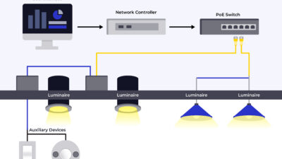
There are two primary categories for addressable lighting controls: room-by-room control and network control. A building can also contain traditional stand-alone line voltage devices and complex theatrical lighting control systems. Specifying engineers and designers should have a system that allows for a clear understanding of which system is intended to be used. In a room-by-room configuration, it is common for an addressable relay module to control a large group of luminaires, which is similar to the way relay-based controls worked in the past (see Figure 2).

Designers can simply show the traditional line voltage devices and let vendors and contractors substitute for addressable systems if they feel those systems have a financial advantage. The downside to this approach is that the specifying engineer or designer loses some control over the components that are provided and making new requests during shop drawing review is not fair to the vendor and contractor. Another downside to this design approach is that the control systems being submitted weren’t coordinated with the owner and users during design.
The traditional method of showing a “$” at the doorway may not convey sufficient information for an addressable system. The type of control station — wireless, wired or network — should be conveyed and related to a specification section or material list. Zoning information is also needed, which allows for a correlation between the control device and precise fixtures used. Historically, the industry used linework to indicate zoning but more recently, subscript-based zone indication is being used. Lighting fixture labels also include a fixture ID and a circuit indication when no line-work is used for circuiting or control (see Figure 3).

Sequence of operations
Three-dimensional computer-aided drafting now allows for model elements to contain properties such as voltage, wattage, control association and panel association. Using these modeling tools tends to encourage using a subscript-based control system because the necessary properties can be assigned to both controls and fixtures. Unique symbols can be used to represent line-voltage, room-based, network-based and theatrical lighting control systems to allow for unique specification of the respective components.
One of the main challenges that designers face is developing drawings and specifications that are compatible with all possible or approved manufacturers. This challenge is commonly used to excuse detailed wiring diagrams, which results in a performance specification for addressable lighting controls. This approach does allow for flexibility as technology evolves and new feature sets are added. The primary downside to a performance specification is that designers may not understand how the systems actually work, reducing their ability to assist the client with design and troubleshooting.
Narrative descriptions of lighting control schemes, sometimes called a sequence of operations, are becoming more common. Each room, area or space gets a sequence tag or label on the floor plan. These labels correlate to a sequence of operations table that is commonly located on the same sheet as the luminaire schedule. It’s easier for vendors to get a complete picture of the control requirements if all of the lighting sequences, schedules and diagrams are grouped together on the same sheet(s).
Sequence of operations tables can be mostly narrative or can look like a matrix. The benefit to a matrix approach is that designers get a predetermined list of features and options and contractors or vendors can quickly see what options apply to each sequence tag. The benefit to a narrative style is that the designer can tell a story to convey the intent of controls. The following control options are used in a matrix or narrative:
- Manual on/off.
- Occupancy sensor on.
- Vacancy sensor off.
- Daylight sensor dimming or multilevel.
- Time-delay off.
- Receptacle control.
- Heating, ventilation and air conditioning control.
The sequence of operations can also reference details to convey the arrangement and labeling of button stations. These button station details should be coordinated with the client during design. Button stations can be on/off, dim up/down or offer preset selection. Each sequence can reference a unique button station detail or, in some cases, button stations can be the same for multiple sequences.
When the types of controls available are more complicated or require multiple scene selections, a graphical interface may be recommended. Common applications include conference rooms, large meeting areas, large open areas or any space with multiple scenes or control zones. Graphical screens have evolved from the monochrome LCD of old. Full color touch screens with programmable pages are the norm now and designers will need to describe what the client wants on each screen or page.

Addressable lighting systems
Addressable systems use low-voltage cabling, typically Category 5E or 6 for power and communication between the controls, hubs and power packs. This cabling is typically run open as opposed to line voltage in conduit or other approved raceways. Designers need to ensure the specifications cover the installation requirements for low-voltage controls.
The hubs and modules that interface with the controls connect to standard 4-inch square junction boxes with knock-out connectors. This separates the low voltage wiring from the line voltage wiring. The downside is that the low-voltage cabling and connectors are external from the enclosure and typically lack strain relief. This presents a concern for the reliability of the control system (see Figure 5). Ideally, the controllers would be mounted in consistent locations within the space, such as above entry doors, so maintenance personnel can locate the connections.

Designers can specify appropriate locations for controllers and require strain relief for low-voltage connections. Referencing the Construction Specifications Institute Division 27: Communications Manufacturers sections for installation requirements is an option, but those sections do not account for CAT 5E connections being made above ceilings on the side of junction boxes.
The importance of system commissioning increases as the system complexity increases. Where projects are broken into phases or installation sequences, multiple programming periods may be required. Designers should include appropriate programming requirements, so that controls are fully functional for the final punch of each phase.
When addressable or network, such as DALI or IEC, control systems are specified, the number of programming iterations can also be specified. Because some clients may not be familiar with modern lighting control systems, it is prudent to specify on-site training for the client. It may be desirable to have a two- or three-month return trip included in the specifications to make adjustments to the control schemes based on user input. System complexity may warrant a service contract with the vendor.
Labelling tends to be a weak point when specifying controls. It is not uncommon to see a bank of four or eight lighting switches without labels indicating what is being controlled. Button stations can include custom engraving to indicate operations or scene names. Designers should meet with users and the client to agree upon naming conventions so that the labels make sense to those using the space. While the labels visible to users indicate function, labels on the backside of covers can indicate the location of hubs and device addresses. As-built drawings can include field-installed locations where typical CAT 5E connections are being made, to reduce troubleshooting time in the future. It can be helpful to building owners and maintenance staff for lighting control hubs and connections to be consistently located in the building. One example would be to locate the addressable relays above the door inside each room.
As systems continue to evolve, engineers and designers need to keep up with changing technology and ensure that the drawings and specifications reference what will be provided. Addressable lighting control symbology should reflect the system components available and the specific options and requirements should be coordinated with the client during design.
The type of lighting control system should be clarified and represented in the lighting sequences. Sequences should provide sufficient detail to allow for all required components to be determined by the vendor during bidding. Lastly, designers should coordinate with the client for labeling requirements and control zones.