Consulting engineers who specify emergency power equipment understand that installations for mission critical facilities, such as hospitals and data centers, are required to comply with NFPA 110: Standard for Emergency and Standby Power Systems in conjunction with codes such as NFPA 70: National Electrical Code (NEC). This article will review the most recent version (2016) of NFPA 110 and offer tips for compliance.

Learning objectives
- Define emergency power supply (EPS) and emergency power supply system (EPSS), Level 1 and Level 2 systems.
- Understand how to apply NEC articles 517, 700, 701, and 702 to NFPA 99 and 110.
- Explain the need for risk analysis in locating the EPS and EPSS equipment, and why coordination with structural and mechanical engineers is crucial in EPS design.
NFPA 110: Standard for Emergency and Standby Power Systems covers the installation, operation, and testing criteria related to the performance of a mission critical facility’s emergency power supply system. A full understanding of the standard is critical for specifying engineers who design such facilities.
Having a full understanding of 2016 NFPA 110 requirements starts with familiarity with the following emergency power system acronyms, used frequently throughout this article:
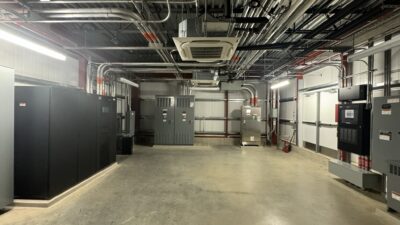
- EPS: emergency power supply. This includes the emergency power source with the calculated capacity and quality required for the emergency supply system (see Figure 1). This can include rotating generators-diesel or propane/natural gas, flywheel generators, steam turbine, or uninterruptible power supply (UPS) systems.
- EPSS: emergency power supply system. This includes the total functioning system of conductors, disconnecting means, the EPS, overcurrent protective devices, transfer switches, controls, supervisory alarms, and support devices-up to and including the load terminals of the transfer equipment to operate safely and as a reliable source of electrical power.
- ATS: automatic transfer switch. Self-acting equipment that transfers the connected load from one power source to another.
- Level 1 EPSS: Installed where a failure of the primary energy power source could result in loss of life or serious injuries.
- Level 2 EPSS: Installed where a failure of the primary energy power source is less critical to life or safety.
- Mission critical: A system that is essential to the survival of a business or organization. When a mission critical system fails or is interrupted, business operations are significantly impacted. Mission critical facilities include data centers, hospitals, laboratories, and higher education researchlaboratories.
It also should be understood that in NFPA definitions, use of the word “shall” is taken to mean “mandatory.” Use of the word “should” denotes a recommendation that is advised but not required.
While the design professional is responsible for assigning the class and level of a project’s EPSS, this decision should be made in collaboration with the owner to confirm the intent of the facility use. For this reason, NFPA 110 does not prescribe assignments. Facility requirements are provided, however, in other NFPA sections, such as NFPA 99-2018: Health Care Facilities Code for health care facilities. It is important to note that NFPA 110 clarifies that it is a minimum standard and does not prohibit equivalent equipment that provides better quality, strength, durability, or safety, among other items.
Chapters 1-3 of NFPA 110 cover the administration and applicability of the standard and define what the standard covers and does not cover. Chapter 2 is a comprehensive list of other NFPA standards and other publications that are intended to work cohesively with this standard. Chapter 3 is a list of definitions that are used in the publication.
This article focuses on Chapters 7 and 8 and concludes with highlights from Chapters 4-6.
Chapter 7: Installation and environmental considerations
NFPA 110, Chapter 7, covers generator installation and environmental conditions. The climate, elevation, and seismic zone of the geographic location are crucial factors to consider, in addition to an indoor or outdoor placement of the generator. The building type and classification of occupancy also affect the design.
State and local codes regarding the installation of emergency generators also affect the design. Some states require that if an EPSS is installed belowgrade, there must be supporting design to minimize damage from flooding, sewer backup, or other disasters. If it is located in an area prone to flooding, structural implications of installing the EPSS above the 10-year flood plane must be considered whether located indoors or outdoors. In such situations, some states require an elevated structure for the EPS and EPSS equipment. State and local codes also must be consulted to confirm acoustical considerations at the property line. Standby EPS may have different requirements from prime-mover EPS installations.
Regardless of the design, remote power-off pushbuttons are required to be located on the exterior of the enclosure and outside the EPS room in an indoor location. Location of remote annunciators also should be discussed with the owner. A custom alarm is recommended for remote power-off to be annunciated to alert the facility that the generator is offline if not located in a secure location.
Indoor generator rooms (EPS) must be in a 2-hour-rated room for Level 1 installations if they are rated more than 1,000 amps and 150 V or greater phase-to-ground. EPSS distribution, ATS, and generator operation and maintenance (O&M) manuals are the only items allowed in this room. If there is an outdoor enclosure, it shall be suitable for the environmental conditions, such as wind, rain, snow, and seismic considerations. A Level 1 EPSS also is allowed to be installed in this enclosure; normal branch distribution is not allowed to be installed in the same enclosure or room.
An EPS installed in a non-walk-in outdoor enclosure with a base-mounted fuel tank will raise the generator access to a point that maintenance is not possible without a ladder. In these instances, a raised platform, minimum 36 in. from the generator rails, must be installed with railings and stairs to allow full access to the maintenance doors. If the EPSS (transfer switch equipment) is installed in a custom outdoor walk-in enclosure, the platform requirement is not required. Indoor-mounted EPS must be sized to allow for 36-in. access space on each side for maintenance. Because of the differences in manufacturing, it is suggested that the basis of design’s overall dimensions be part of the contract documents to mitigate issues in construction.
Mission critical EPS/EPSS are required to have monthly, quarterly, and annual maintenance. For a single energy-converter EPS, the designer should be prepared to explain what happens to the facility if a utility or interior distribution failure calls for the energy converter to start during a routine oil change, antifreeze replacement, or other maintenance that requires the energy converter to be taken offline. The designer and owner should determine if the facility warrants an N+1 energy converter, 2N paralleling gear, or temporary generator connection with auto-start capabilities. Though first costs are important, this is not a system that should be value-designed down.
For a facility with a programmed growth over a few years to meet the overall master plan, it is important to design the initial infrastructure to have capacity for the future. Therefore, it is common to find generators with an initial load under 30% of the rated EPS capacity. Because exhaust-system wet stacking can occur in these situations, it is beneficial to design provisions for a temporary load bank or a radiator load bank so that, during the testing, the generators can consume greater than 30% load and eliminate the wet-stacking issue. (Wet stacking is a condition in diesel engines in which unburned fuel passes on into the exhaust system, occurring most commonly when a generator runs less than 4 hours at less than 75% load. The word “stacking” refers to when the generator exhaust stack becomes oily and is, therefore, a “wet stack.”)
Structural coordination is required for generators to assure solid foundations are designed and to protect sagging fuel supplies, exhaust piping, and conduit from damage at joints. The concrete bases for the EPS shall be a minimum of 6 in. above the finished floor to assist with lubricating under the EPS. Vibration analysis should be completed by the structural engineer, and an isolated foundation base shall be required to eliminate vibration throughout the structure from affecting other floors.
Coordination with a mechanical engineer is required for indoor locations. Air for the generator combustion-air requirements shall be installed per the manufacturer recommendations. Ventilation air for the EPS must be direct from outside in a 2-hour enclosure for Level 1 installations. The outside airflow must be designed for the rated load of the EPS. Fire dampers, shutters, or other automatic closing devices for supply- and exhaust-air ductwork are not allowed for a Level 1 installation. Exterior louvers must be designed for prevailing winds that might blow against the radiator fan discharge air. EPS with unit-mounted radiators must be flex-connected to the exterior louver boot.
Plumbing coordination shall include floor drains and hose bibs inside the Level 1 EPS room. Liquefied fuel, such as diesel, can be piped from an interior day tank or be base-mounted. Interior fuel tanks are restricted to a maximum of 660 gal. One of the more controversial requirements is the Level 1 requirement for 96 hours of fuel capacity. For health care occupancies, the Joint Commission accreditation for hospital organizations has clarified that the intent is to have a plan for providing 96 hours of fuel capacity, not to have a 96-hour onsite storage capacity. Local fuel suppliers must be reliable and able to provide a plan to certify this will be provided. This is an important risk-analysis discussion to have with the owner. In addition, because environmental conditions can shorten diesel fuel life and cause organic growth in tanks and lines, a plan should exist to replace the fuel, or a fuel-polishing system should be used (to keep the fuel refreshed) if the fuel is not consumed every 3 months. When using a refueling plan with a 660-gal tank (diesel, indoors or out), NFPA 110 states that diking or remote impounding are not required, unless the authority having jurisdiction states otherwise.
Elevation differences between a main tank and the day tank or base-mounted tank can be problematic if not designed properly. In certain unique installations, an elevated fuel oil tank (above the diesel generator cylinders) can cause excess fuel-line pressure (head) that a check-valve failure could irreparably damage the EPS. Special considerations from a plumbing design must be done with EPS manufacturer approval to eliminate a single-component failure from damaging the generator. Close coordination is required with the generator vendor.
NFPA 110 also clarifies that fire suppression systems in EPS rooms shall not be carbon dioxide, halon (inergin), or automatic dry-chemical. Exceptions exist if combustion air is indirectly connected/ducted to the EPS combustion intake.
Chapter 8: Routine maintenance and operational testing
NFPA 110, Chapter 8, covers ongoing maintenance and testing. The design must be done in cooperation with the owner to determine the risk assessment of a single generator, provisions for a temporary generator, and paralleling generators that will provide reliability and redundancy in case of a component failure (generator, ATS, generator distribution gear). The owner must be able to perform the following tests with minimal disruption to the facility:
- Diesel EPS energy converters must be tested annually under building load with supplemental load banks as required at not less than 50% of rated (nameplate) kilowatt load. This test shall be 30 minutes in duration.
- Spark-ignition EPS shall be exercised once a month with the available building load for 30 minutes.
- Where multiple ATS are installed, they shall be rotated to verify each start signal is functional.
- Level 1 EPSS circuit breakers shall be exercised annually.
- A Level 1 EPSS shall be tested continuously for its class but not to exceed 4 hours.
Chapters 4-6
The actual EPSS design can begin after there is an understanding of the program, the installation, and the owner’s testing and maintenance requirements. As part of the plan development based on NFPA 110, Chapter 4, the class, type and level, preliminary block kilovolt-amps load-sizing criteria, and the number of ATS branches can be determined. The designer should keep in mind the owner’s criteria for reliability. Can a failed transfer switch serving critical-branch loads on a patient floor eliminate all critical-branch loads, or would two critical transfer switches serving half of the floor provide a more acceptable reliability of the EPSS?
NFPA 110, Chapter 5, provides a description of the EPS energy sources, converters (flywheel and UPS), and accessories. Based on the level and building type/occupancy, a recommendation can be made to provide diesel rotary equipment, gasoline rotary equipment, or liquefied gaseous rotary equipment, as well as temperature maintenance and EPSS capacity. NFPA 70-2017: National Electrical Code (NEC), Articles 700 through 702 describe typical Level 2 installations and requirements for Level 1 as well. Specialty Level 1 health care occupancies also refer to NEC Articles 700 through 702, NEC Article 517, and NFPA 99. Consideration of and familiarity with all these requirements are needed by the design professional. The design professional also must determine if the EPS is designed as a separately derived or non-separately derived system to design the grounding and bonding according to NEC Article 250.
NFPA 110, Chapter 6, describes the transfer switch equipment as the design relates to the number of essential branches. ATS shall, upon loss of utility power, send a signal to the generator to start within 1 second, and depending on the class, deliver power to the transfer switch from the EPS power source. Logic to monitor restoration of utility power is integral to the ATS and shall return the source to the normal (utility-source) branch. When the generator is sized for required loads, but the owner elects to add additional loads not code-required for effective facility operation, there shall be electronic-monitoring logic to measure the total load from the EPSS and load shed nonessential loads to assure the generator is not overloaded. There is also a description of the bypass-isolation ATS that is recommended for Level 1 mission critical facilities. This feature allows the ATS to be manually bypassed to maintain or test the ATS. Nonautomatic transfer switches (NTS) have electric motor operators for the ability to manually add these loads into the EPSS system either at the NTS or from a remote location. Manual transfer switches have no motorized operation and can only be added into the EPSS by physically changing states at the transfer switch.
Protection and selective coordination are described in NFPA 110 as well as in NEC Article 517 and Articles 700 through 702. The entire EPSS must be designed for the available load and braced for the available fault current from the normal (utility) branch and the EPSS. The ATS usually have a very specific list of overcurrent devices that can be used to achieve a series rating. With a distribution system and EPSS system that must be competitively bid, this can be very problematic for the designer if a careful review of shop drawings is not done. Because electrical distribution and EPSS shop drawings often are received at separate times, it is very important to look at the shop drawings as a total system and not independent reviews. Very clear direction should be given in the documents for the basis of design, and a power system study should be performed by the switchgear vendor showing compliance with all power system distribution and EPSS equipment. It is recommended to delay shop-drawing review until this power system study is confirmed to eliminate costly field changes.
Recommendations and guidelines for EPSS equipment, wiring methods, and ratings are provided in NFPA 110 as well as in NEC and NFPA 99, with NFPA 110 also providing the maintenance criteria for end users to properly test, document, and prove compliance to all regulators. As the starting point for every EPSS design, NFPA 110 provides technical guidance for EPSS specification and testing-laying out the important framework for the design professional.