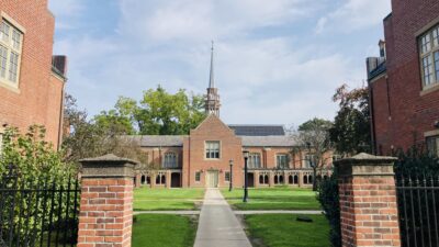
Figure 1: A view from the north shows the wood-encased main concert hall with atrium. The atrium’s mullions are heated with 120-F water to prevent condensation and help heat the atrium. Photo: Paúl Rivera/archphoto
View the full story, including all images and figures, in our monthly digital edition
The Experimental Media and Performing Arts Center (EMPAC) at Rensselaer Polytechnic Institute (RPI), Troy, N.Y., is the world’s largest multi-use space that combines scientific research, technology, and the performing arts. The 222,000-sq-ft building opened in October 2008, after nearly seven years of construction. The high-tech center is situated on a 45-deg hill overlooking the Hudson River on the edge of RPI’s campus. It houses a dual program that features a world-class concert hall and flexible spaces for experimental media performance and research. (see Figures 1 and 2 )
View a time-lapse video of the construction of the EMPAC building here .
EMPAC accommodates both world-class performances and cutting-edge research supporting the performing arts. The realms of science and art are allowed to intermingle freely within the building.
EMPAC’s structural and MEP systems had to balance a number of competing demands for acoustics, air quality, comfort, and energy efficiency.
Figure 2: This is a view from the south of the performing arts center where the 400-seat studio and two black-box studios are located. Photo: Paúl Rivera/archphoto
Furthermore, these needs had to be met in all of its performance and research venues. Whereas most typical performing arts centers have only one primary setting, EMPAC has five. In addition to the main concert hall ( Figure 3 ) EMPAC has a 400-seat studio theater ( Figure 4 ), two flexible black-box studio spaces ( Figure 5 ), and an atrium ( Figure 6 ). Assuming that multiple venues with diverse needs might be operating simultaneously was a key factor in the design.
The acoustics consultant required that the performance venues in the new building adhere to the background noise criteria of RC-15. The RC-15 rating is at the threshold of human hearing, which means that a performance space built to the RC-15 criteria has no perceptible background noise.
Condensation control
The building’s largest component is a vast atrium, nearly 100 ft high, which wraps around the concert hall. The architect’s vision included a glazed north facade without cross bracing and with minimal use of supporting steel.
Figure 3: The 1,200-seat main concert hall is the centerpiece of the EMPAC building. Photo: Paúl Rivera/archphoto
Although this design created a clean and transparent enclosure for the main concert hall, it introduced the challenges of condensation and heat loss. Because the winter months can be extremely cold in Upstate New York, the engineers designed the building for a design condition of -10 F. The atrium was outfitted with a combination of two systems: a displacement ventilation system to move low-velocity air through the space, and a mullion system integrated with hydronic heating to provide space heating and to keep condensation off the glazing. (See sidebar “Heated mullions,” page 20.)
Balancing acoustics and energy efficiency
World-class acoustics standards set the benchmark for the MEP systems in the 1,200-seat concert hall, which is EMPAC’s centerpiece.
The interior of the concert hall has a shoebox form, optimized for symphonic music but with adaptive acoustics to suit all performance uses. The 400-seat black-box theater is a hybrid of a traditional fly tower/audience chamber configuration and adaptable studio design.
To achieve this, while creating an environment of optimal comfort, displacement ventilation systems were designed for both the concert hall and the theater.
Figure 4: The 400-seat studio theater features displacement vents, which provide high-quality air at a low velocity to the theater and concert hall. Photo: Paúl Rivera/archphoto
These systems consist of individual grills with diffusers under each seat and air plenums below, so air is released at a low velocity. (See sidebar “Displacement ventilation systems,” page 22, and Figures 11 and 12 , for more information.)
Driving the displacement ventilation systems is fan wall technology, which is relatively new. Instead of a large centrifugal supply fan, multiple direct-drive fans were installed in a parallel arrangement. The fan wall option provides a number of advantages:
• It reduces noise throughout the system by about 20%, especially the lower sound frequencies, which are trickiest to eliminate.
• It allows greater redundancy while increasing spatial efficiency.
• The direct drive fans are arranged to promote better laminar flow ( see Figure 7 ) and less distance is needed for the air to straighten before it hits the other air handling unit components. Most other fan arrangements need an area to allow the air to straighten up so that it can evenly pass through the cooling and heating coils.
Figure 5: One of the two multi-purpose studios that support rehearsals and scientific research. Photo: Paúl Rivera/archphoto
• The fan wall system also provides redundancy. If one fan goes down in an air handler, the air handler can continue operating with the remaining fans. Hence, performances (and revenue) are protected.
As in the concert hall, a displacement system was used for the 400-seat theater. While the concert hall is the shape of a shoebox, the theater features a tall fly tower above the stage at one end. In order to isolate the stage from the seated areas of the venue, a separate overhead ventilation system was developed above the stage and fly tower. Vents were installed on the roof above the fly tower to release smoke in the event of a fire exhaust.
Perhaps the biggest challenge was the need to create a high degree of flexibility in the media studios while maintaining the same performance quality as the rest of the building. The studios are multi-use spaces for both rehearsal and scientific research in a variety of fields, such as virtual reality, scientific visualization, and human/machine interfaces and interaction.
Figure 6: The multistory atrium has bridges for access to the two-story main concert hall. Photo: Paúl Rivera/archphoto
Regardless of how the studios were being used at any given moment, the RC-15 acoustic standard had to be maintained whether there were two or 200 people in a studio. To address this challenge, a ventilation system introduces air quickly and noiselessly to the studios through custom-design nozzle outlets. The outlets are located just below the wire grid that holds the equipment and the lighting system in order to prevent the lights’ heat from warming the air. Exhaust air is removed from the studios at high levels above the lighting zones.
Since both of the studios were designed to support very high occupancy and equipment densities, they have high electrical and cooling loads. The spaces are designed in accordance with National Fire Protection Assn.’s Standard 13, the standard for the installation of sprinkler systems.
Finally, the studios also had to accommodate the use of multiple projectors at once. Because projectors create additional heat and noise, they had to be isolated. Therefore, each projector was encased in an individual “pod” and connected to flexible ducts that can adjust air diverted from the space. Each studio space can therefore accommodate up to 10 projectors in use at once without any negative impact on noise level or occupant comfort.
Figure 7: A computational fluid dynamics rendering shows the laminar air flow in the research studio. Source: Buro Happold
Acoustic isolation of spaces
To maintain acoustic quality throughout the building, each venue was physically separated from one another and from the plant room.
A box-in-box construction acoustically isolates the four venues and the ventilation systems from the conditioned spaces (see Figures 8 and 9 ). For additional isolation, each of the venues is a concrete box that is wrapped in a secondary structure. The structures prevent sound from travelling between the equipment rooms and the performance spaces, as well as back and forth from one performance venue to the next. The number of holes that penetrate each “box-in-box” structure for cabling and HVAC systems was minimized as much as possible in order to limit the potential for noise transmission.
Figure 8: This BIM rendering is of the main concert hall. Source: Grimshaw
A combination of physical acoustic barriers, sound attenuators, fan wall technology, acoustically treated ductwork, and anti-vibration hangers prevent cross-talk, breakout noise, and plant noise transmission. Rather than using control dampers at end terminals in each venue, active dampers and balancing further block noise from entering the performance spaces. The balancing dampers were positioned much further down the system than is typical to prevent noise transmission.
Their location is acoustically acceptable yet easily accessible for commissioning and other purposes.
Figure 9: The placement of the 400-seat theater and the two studios are shown in this BIM rendering. Source: Grimshaw
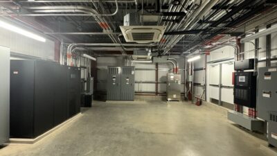
The two HVAC equipment rooms also have a box-in-box construction that acoustically isolates the ventilation systems from the performance spaces. Although it is always best to locate the ventilation equipment as far away as possible from the performance venues, one room had to be located under the concert hall stage.
To contain noise, this entire room is wrapped inside a separate steel structure. For additional sound protection, both the steel structure and the ventilation ducts are lined with two layers of gypsum board, which helps to minimize sound transmission.
The second mechanical room services the studio areas and is located on the upper levels of the building. Studio 2, which is located near this second mechanical room, has a buffer plenum to block noise.
Figure 10: The heated mullion system shows the flow of water that heats the atrium, while reducing condensation on the atrium’s windows. Source: Buro Happold
The benefits of technology
Computational fluid dynamics (CFD) was instrumental for predicting and resolving the challenges of EMPAC’s complicated spaces. This technology was especially useful for the concert hall and the theater, which were the most difficult to design. Both spaces have a variety of conditions:
The concert hall has a stage and a balcony, and the theater has a tall fly tower. In both venues, the engineers had to balance RC-15 acoustics requirements with heating and cooling needs.
CFD software was used to calculate the air temperature and velocity needed to ensure conformance with the building’s strict acoustic criteria. CFD was also vital in detailing the amount of air that would be necessary to offset the lighting loads, which differ dramatically throughout the building.
Figure 11: The main concert hall has swirl diffusers for displacement ventilation. Photo: Buro Happold
It also helped to map air movement and comfort conditions, showing engineers how air would be delivered and distributed. CFD software was especially helpful to the client who wanted to see how the system would work before it was installed.
As one example, CFD enabled engineers to study how to remove air from the concert hall. Instead of pulling hot air across the balconies, they decided to remove most hot air from the front of the stage. This solution means that the warmest layer of heat exits the concert hall from a high level inoccupied space over the stage, causing the least amount of discomfort to the people attending a performance.
Figure 12: The warmed fresh air passes through the pressurized raised floor plenums and rises to the ceiling of the 400-seat theater. Photo: Paúl Rivera/archphoto
In addition to CFD, BIM software helped the team coordinate the complex, non-repeating structures in the building and ensure the full coordination between the structural and MEP systems. All of the equipment rooms and distribution rooms around the concert hall were drawn 3-D during the design phase, which helped thread the ductwork through the structure. The engineers also insisted that the shop drawings be 3-D. These drawings were then used for fabrication, and the contractor also used the 3-D model during construction. To identify and remedy potential collisions prior to construction, the engineers used both manual systems and automatic clash detection. In addition, the engineers designed the MEP and structural systems side by side—in the same office—which helped to minimize problems and facilitated coordination during all stages of the project.
Building for the future
EMPAC integrates both world-class performance and flexible research facilities into one building. The MEP approach combines proven systems, new technologies, and customized solutions that respond to the unique and challenging requirements of this one-of-a-kind facility.
Author Information
Gallagher specializes in environmental engineering and has contributed to sustainable design projects around the world. In 1993 Gallagher joined Buro Happold, where he is the partner and MEP regional discipline leader responsible for the day-to-day operations of the MEP, sustainability, and building analysis teams.
Heated mullions
To heat the north fa%%CBOTTMDT%%ade, a structural mullion system was constructed with circulating hot water. Although somewhat rare, this technology was first developed in the United States in order to cool steel structures in case of fire. It was then refined over the next 30 years in Germany, where it has been used for heating and cooling buildings.
Heated mullions resolved the challenge of keeping the surface of the large north fa%%CBOTTMDT%%ade uncluttered while providing uniform and efficient heating to the internal atrium space. For structural reasons relating to the size of the structure, the mullions are made of steel rather than aluminum.
The mullions are heated by hot water that circulates within the steelwork; glycol is added to the water as an anti-freezing agent. Supply and return pipes are located at the bottom of the fa%%CBOTTMDT%%ade and the air vents are on top to allow air in the piping to be purged prior to balancing. The steel plates have orifice holes of varying sizes to maintain an even flow of water throughout the system. In addition to the heated mullions, the atrium has a displacement ventilation system that helps to offset down drafts and move the air around the atrium slowly. Air is returned at a high level at the top of the atrium and recirculated if needed.
Displacement ventilation systems
Displacement HVAC systems are used throughout the EMPAC spaces, but they serve the most important functions in the concert hall and theater. The key considerations in these spaces were the maintenance of world-class acoustics, coupled with the supply of high-quality air.
In a displacement HVAC system, ventilation air is supplied at low velocity from pressurized raised floor plenums. Here, the supply comes from grilles located under each seat and spreads out across the floor to form a reservoir of cool, fresh air. These heat sources generate a buoyant thermal plume that rises upward and causes a slight suction that draws up fresh air from below. The warmed and rising air is exhausted at ceiling level along with the heat generated from performance lighting and performance equipment. The resultant ventilation system is efficient and comfortable for the audience and performers.
The displacement HVAC system is much quieter than a standard ventilation system. In fact, it is virtually imperceptible to the audience. It also results in increased air quality because fresh air is coming from the bottom up, rather than being pushed from the top down through stale air. Overall, a displacement ventilation system achieves approximately 15% to 20% greater efficiency over a standard ventilation system.