Sequence operations provides a clear, concise and client-friendly method of communicating lighting design intent
Learning Objectives
- Understand the advances in lighting control technology and code requirements that have transformed lighting design since 2012.
- Learn how to implement a sequence of operations approach.
- Know and exploit the benefits of sequence of operations.
Advances in lighting technology and continued adoption of stricter energy codes have changed the way electrical engineers design lighting controls. In states that have adopted International Energy Conservation Code 2012 or newer (which is most of them), traditional wall switches are becoming a thing of the past. In their place, digital lighting control systems have emerged as the solution of choice to maximize energy savings and satisfy building codes.

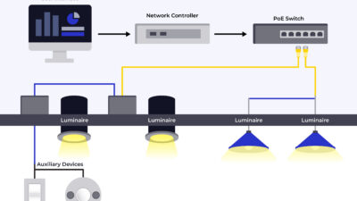
For nonresidential buildings, lighting is controlled by smart networks of “internet of things” devices — relays, occupancy/vacancy sensors, photocells, button stations, touchscreens, etc. — that optimize lighting conditions and energy use dynamically according to performance-based design parameters.
As a consequence, electrical engineers have had to reinvent how to communicate design intent to contractors and clients. Rather than specify lighting equipment to be installed, engineers now specify functional rules for how the lighting system is intended to operate. How long should office lights stay on after the occupancy sensor stops detecting movement? How bright should lighting become when a person reenters? These kinds of questions are now addressed by code, and they must be addressed in design documents.
This is the central problem of lighting design in the age of energy-conscious building codes. While codes mandate that we must specify the function of lighting systems, they do not tell engineers how. Each design firm is left to its own devices when devising a system for communicating lighting system function. The result is a mishmash of styles of documentation, a lack of efficiency for designers and potential missed opportunities for competition among subcontractors.
At LEO A DALY, we’ve put considerable effort over the last few years into updating and standardizing our lighting control documentation. Our approach, known as the sequence of operations, provides a clear, concise and client-friendly method of communicating design intent when specifying lighting control systems.
A brief history of smart lighting code
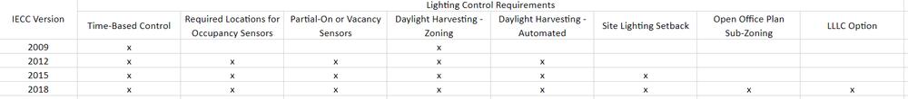
The history of smart lighting controls in code begins with IECC 2012. Before this code iteration, smart lighting controls were in their infancy. While technologies for digital monitoring and control of lighting systems existed, they were not required by code.
IECC 2012 introduced new requirements for occupancy sensors, limiting operation in many spaces to vacancy (manual-on, automatic-off) or partial-on functionality. A partial-on approach saves energy by automatically activating lights to a set output, commonly set at 50% to satisfy code. Occupants may use manual controls to raise light levels to full, but in many cases they won’t if a lower light level is adequate for their tasks.
IECC 2015 introduced or expanded several more requirements aimed at cutting energy.
- The occupancy sensor-based shut-off requirement, which enables automatic shut-off of lighting within 30 minutes of all occupants leaving the space, was expanded in 2015. IECC 2015 added to the list: restrooms, storage rooms, janitorial closets, locker rooms, warehouses and any space 300 square feet or less that is enclosed by floor-to-ceiling partitions.
- IECC 2015 removed the 2012 lighting reduction exception that allowed an occupancy sensor to be used in lieu of light reduction controls. In 2015 code and later, both occupancy sensors and lighting reduction must be used.
- Daylight-responsive control function was added as a new requirement in IECC 2015. Artificial lights in spaces adjacent to windows and skylights must automatically change their output in response to daylight conditions. In these spaces, photo sensors measure reflected light in the room on a continual basis and provide feedback to the smart lighting control system, which then supplements with artificial light until a threshold has been met. This saves energy by expending just the right amount of light, but no more.
- The exterior lighting setback requirement, added in IECC 2015, saves energy in two primary ways. For decorative applications, exterior lighting is required to be dimmed immediately outside of business hours. Where needed for safety, exterior lighting must be shut down an hour after closing, to resume an hour before opening.
IECC 2018 added a “sub-zoning” requirement for open plan office areas larger than 300 square feet. C405.2.1.3 occupant sensor control function in open plan office areas requires open plan offices to be broken down into separate control zones, each of which can be controlled individually or all together.
Technological impacts of code changes
The overall result of these code changes is that traditional lighting controls are no longer suitable for many building types. Starting with IECC 2012 and, in particular, with the vacancy/partial-on requirement, a higher level of sophistication and intelligence was required of lighting controls.
A number of competing smart lighting control solutions emerged, with one thing in common: they all use data rather than power to control lighting function. Instead of a line-voltage wall switch, lighting began to be activated and controlled by a networked system of low-voltage devices. Rather than communicating on/off by the absence or presence of a circuit, devices received packets of data delivered through low-voltage cabling. In place of a relatively “dumb” analog system, these lighting systems operated digitally and were required to have some form of “intelligence.”
In the U.S., each manufacturer of smart lighting equipment uses a proprietary language and equipment to communicate the data needed to control the lighting. Unlike the past, there is no “standard” switch. Pieces and parts from different manufacturers cannot be mixed and matched. The choice of a vendor for the lighting control system is a decision with long-lasting impacts. Electrical engineers specifying these systems must be familiar with the capabilities and limitations of every system in order to properly advise clients and contractors.
Why a sequence of operations?
Before smart lighting controls, electrical engineers specified lighting equipment without paying a lot of attention to how that equipment was used. Energy codes were lax enough that control systems were specified and installed with default settings. And the equipment was simple enough that there wasn’t a lot of functional information to communicate to the contractor and user.
All that has changed. Energy codes are more demanding, the functionality of lighting control systems is complex and solutions vary significantly between manufacturers. One manufacturer might use 10 parts to achieve the desired functionality; another might use six. One might use Cat5 cable; another communicates wirelessly. Engineers should consider the following parameters:
- Function: Can the lighting control do what the code requires?
- Performance: Will the system be optimized beyond “default” settings to achieve design intent?
- Support: Which vendors offer the most robust support in the client’s geographical area?
- Cost: Can competition among vendors reduce the client’s cost?
- Efficiency: How efficiently can design time be used across multiple projects?
- Accuracy: Is the specification process set up to avoid errors and omissions?
Specifying using a sequence of operations satisfies all of these criteria.
A sequence of operations is a document, added to the end of the drawing set, that specifies the functionality of the lighting control system. Using a spreadsheet, each space in the floor plan is identified according to a three-letter code. Each code is given a set of rules that must be followed in order to maximize energy efficiency and optimize the utility of every space according to the client’s needs. The sequence of operations is supplemented with a section in the general specifications identifying vendors and products that have been vetted by the design team.
Many engineering firms use a standardized sequence of operations on every lighting design project. This provides clear instructions for subcontractors on the function needed to meet code and the performance needed to meet aggressive energy-savings goals. It then becomes the subcontractor’s job to select vendors from the electrical specifications that are known to provide adequate support in their specific geographic region. When bidding on the project, subcontractors are forced to compete on cost. And because these documents are standardized and kept up-to-date continually, engineering teams are able to operate efficiently and avoid errors and omissions (accuracy).
There are other ways to specify smart lighting controls. Engineers have the option to specify exactly which vendors and equipment to use, starting from scratch on every project. But for many designers, the benefits to using the sequence of operations method are simply too great to ignore. It takes a little upfront time to do the research necessary to standardize the sequence of operations and electrical specifications, but it pays off in both the short term and long term.

See example of the plan component of the sequence of operations in this .pdf. Page 2 shows an example of the plan component of Sequence of Operations. Page 3 shows an example of the schedule component of sequence of operations.
Setting up the sequence of operations
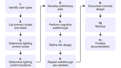
The sequence of operations is an organized, standardized way of communicating the functional requirements for every space included in a lighting design project. It includes three main components: The plan component, schedule component and specification component. The following is a narrative explanation of each component, and the visual examples are indispensable to understanding how it works.
Plan component: The first layer of information in a sequence of operations is given on the electrical floor plan. The plan shows the circuits and electrical systems as usual, except that it does not specify every component in the lighting control system. The exact locations and types of relays, sensors, photocells, power packs and junction boxes are omitted. Because these components vary between manufacturers, engineers leave these specifics up to them to create a set of plans to meet the design intent.
To ensure convenient access to occupants, the plan does specify the location and type of manual lighting control devices in each space. With each manufacturer offering an array of different manual control options, designers want to ensure that the final product best meets the client’s needs
In place of detailed wiring diagrams and components, each space is tagged with an oval containing a three-letter code unique to that space type. For example, open offices are tagged with OPN; enclosed offices with OFF; lobbies with LOB, etc. These three-letter codes refer the reader to the schedule component, which contains the functional information needed to meet design intent.
In spaces that include multiple lighting subzones, such as open offices, engineers add a unique tag in subscript. Where applicable, luminaires within daylight zones are indicated on plans to assist manufacturers in locating photocells.
Schedule component: The schedule is a table at the end of the drawing set that specifies the minimum functional performance of the lighting control system. This gives clients, manufacturers and subcontractors a clear and concise understanding of how the lighting control system needs to behave in order to meet code and design intent.
It is organized in the following way:
- Title: “lighting control sequence of operations.” This is it. The much-discussed sequence of operations.
- Glossary: The first section defines abbreviations used throughout the rest of the table. This allows the table to be condensed enough to provide quick reference on a single page.
- Space type and tag: These two columns identify the three-letter tag with its full name. Every space type and subtype is given a unique code that is then defined in terms of the devices required and their minimum functionality.
- Devices: This column is subdivided into four categories.
- OCC: This sub-column identifies the type of occupancy sensor required in the space type identified. For example, if the OCC column reads DT, a dual technology occupancy sensor (e.g., passive infrared and ultrasonic/microphonic) is required in that space.
- PHOTO: This sub-column, answered in Y/N format, tells whether a daylight harvesting photocell is required in the space.
- NETWORK: This sub-column, answered in Y/N format, tells whether a network connection to the system head-end is required. A network connection allows for scheduled control from the system time clock, remote control and monitors and remote programming.
- UL 924: This sub-column, answered in Y/N format, tells whether egress lighting within the space must be controlled along with space lighting. This allows code-required override control of egress lighting where multiple lighting branch circuits serve the same control zone.
- Sequence of operations: This column is the most important part of the table. It provides specific lighting control rules that must be followed in the space type identified. The section is written in plain English, spelling out the code-required performance of lighting in a way that clients can understand. (e.g., For decorative exterior lighting, “Lights to 100% at 15 minutes before dusk.”)
- Notes: This section provides clarifying information, such as the presumed operating hours of the business.
Specification component: The specification component is the final piece of making the sequence of operations method work for lighting control systems. Where the prior two components provide the functionality required to meet code, the specification component provides a level of quality control to the systems used in the final buildout.
The specification component is a section of the design firm’s master specifications document, which includes a list of approved manufacturers that have been vetted by the designer and are known to comply with code requirements.

Additional benefits of sequence of operations
As more states begin to adopt more aggressive energy codes, it will take some time for the building and engineering industry to catch up.
In summary, sequence of operations:
- Makes lighting controls easier to understand and discuss with clients by divorcing the “what” from the “how.” When talking to a client, most of them will not understand or care how the specific solution achieves its results. They care about the results themselves. With sequence of operations, designers have a plain-spoken method to show the client how the building will operate. Anyone can read the sequence of operations and know immediately what will happen in any space, making it extremely easy to make decisions and achieve the right design intent.
- Is manufacturer-agnostic. The “old way” limits competition by locking contractors into an overly specific solution.
- Saves more energy. With device settings identified on a room-by-room or task-by-task basis, clients have greater control over the part that matters — the function. This allows clients to pursue more aggressive efficiency strategies by giving more complex control over spaces. If the client sees an opportunity for greater optimization, it’s easy to just create a new three-letter tag and dial in customized settings for that room type.
- Makes engineers more accurate and efficient. Once a standard sequence of operations has been developed for one project, it becomes extremely efficient for it to be used on future projects. In addition, it avoids errors and omissions that could be caused by starting from scratch every time.
- Simplifies commissioning. Instead of being given a list of parts and having to deduce the design intent, commissioning agents know immediately how the space is supposed to function. In addition to making the commissioning agent’s job easier and faster, it helps designers avoid calls for clarification from the field.
- Keeps design intent information out of the spec. There are other ways to communicate design intent with smart lighting controls; one option is to include the system’s function in the master spec. Because most contractors do not carry a copy of the spec into the field, this can cause ambiguity. By locating all functional information on one page, in the plan set, contractors become efficient and less likely to make mistakes.
Energy codes have fundamentally changed and so design needs to change too. One way or the other, designers need to be able to describe to clients and builders not just what equipment needs to be installed, but how it needs to function. Sequence of operations accomplishes this.
How to create in-house specifications
Not all lighting system types are included in a master specification, so firms may need to produce their own
Most design firms use AIA MasterSpec, the industry-standard product research and specification resource for design professionals. Developed by Deltek, MasterSpec has more than 900 master guide specifications covering more than 7,000 products and is the most comprehensive and trusted collection across architecture and design. However, at the time of writing, it does not cover all of the system types we most commonly use.
To overcome this, LEO A DALY conducted a thorough review of the lighting control systems available through major manufacturers and created its own specification titled, “Addressable lighting control systems.” This required personal outreach to sales representatives from several lighting control manufacturers, a detailed analysis of each of the specifications and the merging of the relevant information into a custom specification for use by our electrical engineers.
While this presents a barrier to entry for engineers unfamiliar with lighting control systems, it is an important step to becoming knowledgeable enough to specify them. Once a firm has gone through the work of developing a custom specification for lighting control systems, only minor updates are needed each year to stay current with the different options from manufacturers.
With the specification component completed, engineers have everything they need to specify smart lighting control systems, meet code and aggressively pursue energy savings for clients. With a thorough specification in hand, clients are free to pursue an open-bid contracting process that encourages efficiency, cost-effectiveness and innovation.