Engineers should know the different types of emergency lighting systems, and best practices for their installation and maintenance

Learning Objectives
- Become familiar with basic code requirements pertaining to emergency illumination, such as where emergency illumination is required and what lighting levels are required.
- Learn about different power sources and controls for emergency lighting, including unit equipment, central inverters and generators, as well as their respective advantages, installation requirements and maintenance considerations.
- Know some best practices for designing and installing emergency lighting systems, including coordination with architects and authorities having jurisdiction.
Emergency lighting insights
- Emergency lighting systems selection is complex, and requires knowledge of various codes and standards.
- Selecting the correct emergency lighting power source is paramount to the correct design, and engineers should consider all options.
During a power outage, whether routine or hazardous, ensuring the safety of building occupants is paramount. Emergency illumination plays a crucial role in providing a safe exit route during power outages or other emergencies, such as fires.
![]() Building codes and NFPA standards set the requirements for emergency illumination. The primary codes and standards for emergency lighting requirements are:
Building codes and NFPA standards set the requirements for emergency illumination. The primary codes and standards for emergency lighting requirements are:
- International Building Code (IBC).
- NFPA 70: National Electrical Code (NEC).
- NFPA 101: Life Safety Code.
NEC Article 700, Emergency Systems, addresses the means for energizing, installing, controlling, testing and maintaining emergency lighting. Chapter 10, Section 1008, of the 2021 edition of IBC indicates the minimum locations where emergency lighting is required. NFPA 101 also indicates requirements for emergency lighting, many of which are duplicated in the building code, as well as detailed testing and maintenance requirements for emergency lighting.
NEC Article 700.16, Emergency Illumination, states that “emergency illumination shall include means of egress lighting, illuminated exit signs and all other luminaires specified as necessary to provide required illumination.”
Where is emergency lighting required?
The IBC generally requires automatic emergency lighting in “rooms and spaces that require two or more exits or access to exits” in aisles, corridors and exit access stairways and ramps. Within buildings, automatic emergency lighting is required in interior exit access stairways and ramps, interior and exterior exit stairways and ramps, exit passageways, vestibules at the level of discharge used for exit discharge and exterior landings for exit doorways leading to the exit discharge, which terminates at the public way.

The engineer should coordinate with the authority having jurisdiction (AHJ) to determine what is considered the public way to confirm how far emergency lighting needs to extend outside the building. The building code also requires emergency lighting within specific rooms, including electrical rooms, fire pump rooms, generator rooms, public restrooms larger than 300 square feet and fire command centers.
NFPA 101 expands emergency lighting requirements, stating that it is needed at doors equipped with delayed-egress locks, sensor-release of electric locking systems in the means of egress, exit access escalators and specific stair shafts and vestibules of smokeproof enclosures.
Many of the rooms, spaces and egress components referenced in the building code requirements for emergency lighting are formally defined in the building code. The engineer should coordinate with the architect to determine which rooms in the building meet these definitions.
It is also recommended that the engineer request egress plans from the architect to review egress paths against the proposed emergency lighting and exit sign layouts. Furthermore, the engineer must coordinate with lighting designers and architects to appropriately select which fixtures should be used for emergency lighting for the desired aesthetic and light distribution.
If the project can accommodate it, it is recommended to be conservative with emergency lighting layouts, providing more than code minimum, not only because it will yield better visibility in an outage, but because interpretations of where emergency lighting and exit signs may be required can vary between AHJs.
It is therefore recommended that the design team include directives in the construction documents and bid forms for the contractor to provide unit pricing for additional emergency lighting, exit signs, UL 924 transfer devices and branch circuiting, in case the AHJ requests additional emergency lighting during construction. At the time of AHJ inspection, however, ceiling installation is likely complete or close to completion and post-inspection lighting and branch circuit installation can be more costly to the budget and schedule than if they were included in the base bid construction documents.
Emergency lighting duration and illumination requirements
The IBC stipulates that emergency power systems are required to provide power to emergency illumination for at least 90 minutes via storage batteries, unit equipment (lighting fixtures with integral batteries and transfer devices), or an on-site generator.

The NEC expands on what may be used as emergency power sources. Per NEC Article 700.12 (C) and (I), storage batteries (such as central lighting inverters) and unit equipment must be able to sustain the total load (power) for at least 90 minutes without the voltage falling below 87.5% of normal battery voltage. Unit equipment, specifically, is also required to maintain at least 60% of the initial emergency lighting output (lumens) for at least 90 minutes. Unit equipment fixture batteries and central lighting inverter batteries typically have 90 minutes of backup as standard offerings.
Increasing power storage capacity for inverters for even longer durations can yield significant increases in the physical size of the battery, the amount of space needed and the cost of the equipment, therefore it is uncommon to size an inverter for more than 90 minutes of battery backup. If an emergency power source is a standby generator, it likely has fuel storage for significantly longer runtime than 90 minutes and can sustain emergency lighting for hours.
The building code defines minimum illumination levels and uniformity during an emergency along the path of egress measured at the floor level. At initial loss of power, an average of 1 footcandle and a minimum of 0.1 footcandle are required. At the end of the 90-minute emergency lighting duration, lighting levels are permitted to be as low as 0.6 footcandle on average and 0.06 footcandles minimum.
In I-2 occupancies, such as hospitals, failure of a single lamp in a luminaire cannot reduce the illumination level to less than 0.2 footcandles in an emergency. To provide a relatively uniform illumination at the floor, the code specifies a maximum-to-minimum illumination uniformity ratio of 40:1, meaning the brightest spot measured at the floor cannot be more than 40 times brighter than the dimmest spot on the floor during emergency lighting operation.
Lighting calculation software, such as AGi32, can be used to simulate emergency lighting levels and verify the illumination parameters defined in the code are met. It is important for the designer running the simulation to check the .ies files used in the simulation against the emergency lighting source. If a central lighting inverter or standby generator is used to power emergency lighting, the normal lighting fixtures’ .ies files may be used.
If unit equipment batteries are used, the designer should check with the manufacturer if they have .ies files for the fixture with illumination data reflecting battery operation. If a conservative emergency layout cannot be achieved, it is recommended that a lighting designer or similar lighting specialist, such as a manufacturer’s representative, perform calculations with a realistic model of the space, including colors, geometries and reflectances proposed for use in the area of study (see Figure 1).

Emergency lighting must be illuminated within 10 seconds of loss of normal power per NEC Article 700.12, General Requirements. Power supply and transfer components in emergency lighting systems must be listed to UL 924.
Choosing the right emergency lighting power source
Depending on the size of the project and occupancy classification, load profile of the building and the size and technical expertise of building staff, certain emergency lighting power sources are better suited than others for the application and project budget. In addition to the first cost, testing and maintenance costs are a significant factor when choosing the emergency lighting power source. Emergency lighting fixtures, regardless of power source, are typically required to be operationally tested monthly for 30 seconds and annually for 90 minutes, per NFPA 101 7.9.3, Periodic Testing of Emergency Lighting Equipment.
Use of unit equipment is often favorable for smaller buildings with limited need for emergency lighting and limited technical staff. Unit equipment are the simplest emergency lighting sources, with an integral light source, battery, charger, transfer device and testing function, which can be manual or automatic. Many emergency battery fixtures now have self-test features, which alleviate the owner’s need to have maintenance personnel climbing up and down ladders and pushing test buttons, monthly.
However, self-test features on unit equipment do not alleviate the need to walk the site, as personnel still must visually observe status indicator lights and document results unless results can be monitored and recorded by a computer-based system (see Figure 2).
An alternative to unit equipment for smaller projects that has a similar cost scale and maintenance impact is a microinverter or mini-inverter. These small inverters are typically sized ranging from less than 100 volt-amperes (VA) to a few thousand VA, depending on the manufacturer and are designed to energize small quantities of emergency lighting fixtures. Due to their size, they can often be wall-mounted. Smaller models even offer options to mount above ceilings or be laid into ceiling tiles.
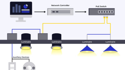
While these inverters are more efficient in terms of the number of batteries required to energize emergency lighting compared to unit equipment, they often require the addition of UL 924 transfer devices to mimic control of normal lighting fixtures on the same zone of control and to monitor the normal lighting branch circuit serving the area (see Figure 3).
As projects become larger, it becomes less economical to use unit equipment or small inverters and project conditions tend to favor use of central emergency lighting inverters or generators for emergency lighting power. Deciding to use central lighting inverters or standby generators may ultimately come down to whether there are nonemergency loads that need to be, or are preferred to be, on a backup power source (i.e., legally required standby or optional standby loads).
If there are standby loads requiring backup power, a generator is typically specified to meet the larger power capacity and longer backup duration required, compared to emergency loads. If serving emergency loads from the generator, a dedicated emergency distribution (automatic transfer switch and downstream panelboards) is installed to serve emergency lighting and other emergency loads throughout the building, separate from transfer switches and distribution for standby loads.
If there are no nonemergency loads requiring backup, it may be advantageous to use a central emergency lighting inverter (or multiple, depending on building size) as first costs, maintenance costs and space needs are higher for generator systems than central emergency lighting inverter systems.

A central lighting inverter is a battery cabinet that is listed as a power source for emergency loads. The physical size and cost of the inverter is largely dependent on the kilowatt rating of the unit, if it is three-phase or single-phase, if it is equipped with circuit breakers and if it has a maintenance bypass section.
Central lighting inverters can also be specified with communications inputs and outputs and can be monitored by building management systems or other external software. Larger inverters are often floor-mounted in an electrical room and are recommended to be installed on a concrete housekeeping pad for resiliency. Central lighting inverters provide a single point of maintenance from a battery backup standpoint, with one point of testing and one set of batteries to maintain and replace, versus unit equipment at individual lighting fixtures or remote-mounted microinverters.
Testing at a central lighting inverter in an electrical room is less disturbing to active spaces than testing at individual unit equipment battery packs (see Figure 4). For example, a maintenance person having to climb up and down a ladder in a busy corridor to test emergency lighting could be avoided by using a central lighting inverter. Like unit equipment batteries, batteries in central lighting inverters typically require replacement after approximately 10 years (more or less, depending on usage and environmental conditions around the batteries).
From a wiring and controls standpoint, using unit equipment battery packs is the simplest and least expensive emergency lighting source. Per NEC Article 700.12 (I) lighting fixtures with integral battery packs shall be energized from the normal branch circuit that serves the area, with an additional connection made to an unswitched portion of that normal branch circuit to monitor normal power status. If normal power is lost, the unit equipment will sense the interruption via the unswitched branch leg and will illuminate its lamps via the battery pack. Another code-compliant option is to feed the unit equipment from a lockable-on branch circuit on the same panelboard as the surrounding normal lighting.
If a central lighting inverter or generator are used as the emergency lighting power source, additional components are introduced at the branch circuit level compared to unit equipment. UL 924 emergency lighting bypass relays and UL 1008 branch circuit emergency lighting transfer switches (ELTS) are used to monitor normal power and transfer to emergency power at the branch circuit level. One of these components is provided per lighting control zone with emergency lighting. For example, a room with two lighting control zones with emergency lighting will have two emergency lighting transfer devices or bypass relays.
UL 924 emergency lighting bypass relays are wired with a normal branch circuit input, an emergency branch circuit input, a normal branch circuit output and an emergency branch circuit output, as well as connections for monitoring normal and emergency power and for controlling the emergency lighting to match the normal lighting on that control zone.
During normal operation, the relay monitors the control (on/off/dimming) of the lighting on the normal branch circuit fed from that relay and controls the emergency fixtures fed via that relay in the same way. When power is lost to the normal branch circuit, the bypass relay detects this and forces the emergency lighting on that control zone to full brightness.
The UL 1008 ELTS is similar to the bypass relay in that it has one normal power branch circuit input and one emergency power branch circuit input, as well as inputs for normal power monitoring and controls, but, unlike the emergency lighting bypass relay, the ELTS only has one branch circuit output. The normal branch circuit acts as the source to the load until the ELTS senses loss of normal power, at which time it switches to the emergency source to maintain power to the lighting served.
Certain bypass relays and ELTSs can be specified with fire alarm dry contact inputs, which can be configured to bring emergency lighting to full brightness upon receiving a signal from the fire alarm system. Bypass relays and ELTSs can be wall mounted, ceiling mounted or mounted above ceilings, if accessible. Many are offered with plenum ratings for installation in plenum ceilings.

Both the bypass relay and the ELTS are required to be accessible for testing and include pilot lights indicating the availability and status of each source. For this reason, it is recommended that the devices be installed on or below ceilings and not above ceilings. Bypass relay and emergency lighting transfer switch models typically have options to support 0 to-10 volt (V) dimming, which is commonly used across commercial lighting systems (see Figure 5).
For more specialized applications, such as theatrical lighting, emergency lighting transfer devices are available for DALI and DMX protocols, which are digitally based and therefore have different wiring topologies than standard non-dimming or 0 to 10 V dimming applications.
Code adherence and reliability
In conclusion, emergency lighting is a critical component of building safety, mandated by building codes and adopted standards. Whether choosing unit equipment, central inverters or standby generators as the power source, the goal is to provide reliable illumination during emergencies in a manner that fits the project’s budget and owner’s maintenance capabilities.
Collaboration with architects, adherence to regulatory requirements and proactive maintenance are key to ensuring the safety of building occupants. By following best practices and exceeding minimum standards, designers can create robust emergency lighting systems that will be there to guide occupants to safety when needed most.