With an enrollment of more than 24,000 students and an annual research budget exceeding $300 million, the University of Illinois at Chicago (UIC) has always been able to attract world-class research initiatives. To continue to do so, university officials knew it was high time to update the university’s laboratory facilities.
Consequently, for design and construction of the campus’ new Advanced Chemical Technology Building (ACTB), they brought together a project team with a proven track record in lab design. Not only did the team prioritize current user needs, they also focused on providing flexible layouts and systems that could easily adapt to future needs.
“Our team fleshed out all the options and coordinated the owner’s priorities with current technologies, the budget and even a number of future variables,” relates Jeff Pratt, a KJWW mechanical engineer on the project.
Thus, the design team of architects, engineers and the owner—including researchers and administrators—began by holding a series of meetings during which a master list of needs and wants was created. Systems that they evaluated included lighting, safety, temperature, humidity, electrical grounding and power, to name a few. And they went into detail, even including issues such as the number of 220-volt vs. 110-volt outlets for miscellaneous laboratory equipment loads.
“From the beginning, the team understood the importance that M/E systems have in a laboratory research facility. Even before the programming was complete, the team had detailed discussions with the users of the facility to understand their needs,” notes Pratt. This allowed for the design of the M/E/P infrastructure to be fully integrated into the architecture of the building without sacrificing performance or safety.
Finally, after a year of meetings and conversations, the group completed the design phase of the new 145,000-sq.-ft. laboratory building for the downtown campus at the beginning of the year, with construction scheduled for completion in 2007.
Lay of the land
In general, laboratories within the facility are composed of one, two, three or four modules, with the grouping and stacking of these modules forming the building’s shape. Building floors are grouped based upon laboratory type and usage, which ultimately will include organic chemistry, biochemistry and chemical science, biophysics and physical chemistry, neuroscience, nanoscience/materials science and laser dynamics. The building also contains a three-story north wing and a five-story east wing with a basement mechanical room and mechanical penthouse.
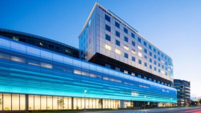
The majority of the building exterior is composed of floor-to-floor low-E glass, which is clear-glazed to optimize daylighting and fritted with an integral dot pattern to control solar gain. Early coordination and analysis by the design team resulted in an optimal glazing and frit pattern in an attempt to closely match the design cooling load with the laboratory-required air changes per hour (ACH). To improve comfort near the glass during the cold Chicago winters, radiant ceiling panels will be installed adjacent to all floor-to-ceiling glass.
As for the building’s air systems, they are divided based upon location and usage. The north wing penthouse contains an air-handling unit (AHU) for general spaces, a cleanroom AHU and a laboratory spaces AHU. Also, a basement AHU is dedicated to a large two-story glass corridor that serves as the main entrance to the building.
In the east mechanical penthouse, there are two more large AHUs that serve the entire east wing. Fume and general lab exhaust are routed to the top of the east wing, manifolded and discharged via high-plume, dilution-type laboratory exhaust fans. All AHU fans are powered by variable frequency drives (VFDs) to benefit from reduced energy consumption at reduced flow rates, as well as to account for filter-loading to maintain laboratory-required ACH. The manifolded exhaust system uses plenum-bypass dampers to allow variable system flow while maintaining high-exhaust plumes.
Due to the ever-changing nature of the research that will be conducted in the building, the mechanical systems were designed with flexibility in mind. For example, the main east wing air systems, sized with an 80% diversity factor to save initial capital, include capacity for future high hood laboratories and changes in airflow as a result of future renovations. Similarly, utilities were routed in a central manner that makes them easily accessible for future connection and extension, as well as changes in capacity.
Inside ACTB there will also be a number of “cleanrooms” that must meet stringent air quality standards. Spaces range from 90 to 240 ACH (with 15 ACH from outside air). All air will be filtered and supplied through high-volume, low-velocity HEPA diffusers. And because these rooms will be using equipment with mercury, a dedicated exhaust system will be installed to close recirculation dampers and send mercury-contaminated air directly to a dedicated emergency mercury exhaust system on the roof in the event of a spill. Most of these rooms will be rated at Class 100,000, while the remaining three will be Class 10,000. With future flexibility in mind, one Class 10,000 space was designed with low return and ceiling space for modular fan filter units that could later increase the space classification to Class 1,000.
Because ACTB will be connected directly to the existing Science and Engineering South (SES) Building, the exhaust air system was designed to avoid contaminating that structure’s intakes and that of any adjacent buildings on campus. Consequently, all exhaust from ACTB is at the highest point in the building. Associated outside air intakes are also located three stories aboveground to minimize pollutants and maximize security.
Not your typical HVAC
In addition to its unique air movement requirements, ACTB also has some special heating and cooling needs. Consequently, a local system was installed to serve seasonal cooling needs and prevent water waste within the building. The system serves three main purposes: user-defined critical environmental cooling needs, physics department laser cooling and chemistry department distillation cooling. The local system serves seasonal cooling coils directly while utilizing heat exchangers to decouple the physics and chemistry loop from each other, as well as from the central system. Users will employ quick-connect hose attachments in their labs to connect to and cool equipment and processes, which saves energy and reduces waste.
For heat, ACTB make uses of the campus’ high-temperature hot-water system that circulates water around campus at 400°F and 300 psi. Heat exchangers decouple the building system from the campus system to bring water temperature and pressure down to usable and safe levels.
The building is also directly connected to the campus chilled-water loop. Local pumps and controls are configured to allow the campus chilled-water pumps to pump chilled water throughout the building if they are capable. When they cannot maintain the differential pressure required, the local pumps will assist the campus pumps to meet the needs of the system.
Campus chilled water, however, is only available when the outside air temperature is above 50°F, and is not necessarily brought online for an excessively warm fall or spring day. This was a large design obstacle. The challenge was met by having the users define critical areas that required cooling year-round. These target areas were then connected to the local cooling system.
Energy payback
Energy recovery was an important part of the design, and a number of technologies were considered. For example, the design team agreed that a total enthalpy wheel would not suit this facility because of the risk of cross-contamination between outside air and fume exhaust. Similarly, heat pipes were ruled out because of the size of the building. Pipes for such a high-recovery application would have been impractical due to their size and the difficulties posed by installation and service. Instead, a run-around loop utilizing glycol water, pumps and water coils located within the outside air and exhaust airstreams was determined to be the best approach for the energy-recovery system because it eliminated the risk of cross-contamination.
But in the end, an energy analysis, performed as part of the planning process to determine if the energy recovery system would provide an attractive payback, ultimately led the design team away from energy recovery. The decreased cooling and heating loads were weighed against the increased fan energy associated with the added energy recovery coils and the added pumping energy. The projected payback period was 13 to 17 years.
Ventilation design was also modeled in the energy analysis. UIC standards initially directed the ventilation design to constant volume supply and exhaust in laboratories. After reviewing potential VAV options with end users of the facility and making them comfortable that the system could vary airflows and maintain pressurization requirements in labs, this was also modeled in the energy analysis to determine payback. Payback associated with additional laboratory controls required for VAV operation was 8.5 years, a payback that was acceptable to UIC officials. The process cooling system was also evaluated as part of the energy analysis and proved to have an even more attractive payback of approximately two years.
Commissioning complexity
Due to the complexity of building systems in the ACTB project, the university has chosen third-party commissioning to ensure that concepts incorporated into the design will be carried on throughout construction. With a commissioning agent going through the building and verifying that all systems are operating as they were designed, the university anticipates that the commissioning process will improve the energy efficiency of the building, minimize startup issues and increase safety.
But most important, the latest engineering technologies will be supporting the work of 180 principal investigators and graduate students as engineering furthers the sciences—now and for years to come.
Electrical Systems: Achieving 24/7/365
As was the case with the mechanical systems, the electrical systems in the University of Illinois at Chicago’s new Advanced Chemical Technology Building have been designed using the holistic approach. The main electrical service into the building is a two-circuit, 12,470-volt, double-ended unit substation with two 3,000-kVA transformers and a main-tie-main 480-volt secondary. With the synchronizing capabilities at the university power plant, this unit substation can tie both medium voltage circuits onto one bus. This allows the university’s engineers to distribute the building’s load evenly across the campus distribution system. The unit substation is designed to provide redundancy for this research-intensive building and ensures continuity of service for long-term experiments and programs.
“This building simply can’t afford to go down. Researchers here will depend on consistent electrical service, heating, cooling, water temperatures, etc.,” points out Pratt. “The team worked together to determine the appropriate level of redundancy to minimize the likelihood of costly system outages.”
In addition, a web-based monitoring and control system is part of the design for the automatic transfer switches and 600-kW emergency generator serving both life-safety and emergency equipment loads. This system will be integrated through the building’s management system for remote monitoring and control by the university’s engineering staff.
To accommodate the high power demands of the facility, each of the research labs has been equipped with either one or two power panels. And due to the sensitive nature of the equipment within the labs, the building is protected by a lightning-protection system, extensive ground plane and cascading transient voltage surge suppression (TVSS).
Lighting the Labs
The the University of Illinois at Chicago’s Advanced Chemical Technology Building features a master lighting control system. Photocell, time clock and light-level sensors interface to provide scheduled on/off times for both interior and exterior areas, as well as daylight harvesting in the two-story common areas with floor-to-ceiling glazing. These controls enable this building to comply with ASHRAE energy requirements. Lighting for this building is a combination of energy-efficient T8 and T5 fluorescent lamps, electronic ballasts and high CRI rating for superior color rendering to accent the unique materials used throughout the building.
To accommodate the light levels required within the labs and still provide flexibility and control, suspended linear direct/indirect fixtures with multi-level switching have been provided.
To create a dramatic exterior appearance at night, the two-story common areas and mechanical penthouse with glass encasement are backlit, adding to the structure’s architectural interest.


