Three transformers serve electrical loads for an office building, data center and mechanical equipment
The design of an electrical distribution system for a confidential client was required for office building loads, data center loads and supporting mechanical equipment loads. The new electrical distribution system design involved coordination with the electrical utility company to replace utility transformers.
The electrical distribution system was fed from three utility transformers: two 2,000–kilovolt-amperes transformers and one 1,500–kilovolt-amperes transformer. Three transformers were installed in a transformer vault adjacent to the main electrical room. Two 2,000–kilovolt-amperes transformers were running in parallel feeding a common secondary bus. The common secondary bus fed an existing switchboard serving existing office building loads and supporting mechanical equipment loads.
The primary of both transformers was fed from a medium–voltage automatic throw-over switch. The ATO was fed from two utility power feeders. The preferred utility feed and the alternate utility feed were each fed from different substations. The 1,500–kilovolt-amperes transformer was dedicated to data center loads. The transformer primary was fed from one utility power feeder. The transformer secondary fed an existing switchboard supporting data center loads through an automatic transfer switch. The ATS was also fed from two 2,000–kilovolt-amperes transformers common secondary bus as an alternate feed.
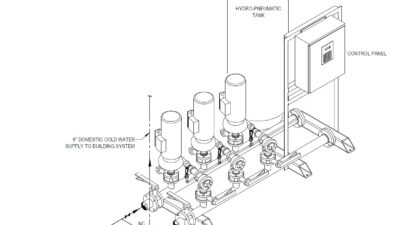
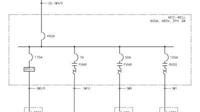
The electrical distribution system supplied multiple switchboards located in different parts of the building. Data center loads and air-handling units were supported by the same switchboard, however, the chiller units, cooling towers, chilled water pumps and condenser water pumps were supplied from different switchboards and a motor control center. The chiller units, cooling towers, chilled water pumps and condenser water pumps were sized to support the data center loads and other building loads.
After completing the field work to document the existing conditions of the electrical distribution system, a design study was developed to address the different available options to install the new utility transformers outdoors. The proposed electrical distribution system design addressed sizing the utility transformers, switchboard, sequence of operation, required modifications to the existing electrical distribution system and equipment layout.
Sizing the utility transformers was a critical challenge because of the limitation of the transformer size offered by the electrical utility and the existing electrical distribution system configuration. It was not feasible for the client to provide its own transformer because the feeders were shared with other electrical utility company costumers.
The electrical utility agreed to provide three 2,000–kilovolt-amperes transformers and permitted two of the transformers to run in parallel as one unit and the third transformer to run individually with a tie on the secondary (see Figure 6). Four issues needed to be addressed as part of the design to achieve proper operation of the transformers:
- Primary protection: Both paralleled transformers were fed from two load interrupters with one normally closed and one normally opened and a tie connection between the two transformers such that only one load interrupter is feeding both transformers at any given time and will trip open if a fault occurs on the secondary side upstream from the secondary protection of either transformer. The third transformer was fed separately from a third load interrupter that is normally closed.
- Secondary protection: Each of the two paralleled transformers had a motorized circuit breaker on the secondary side. Both circuit breakers were electrically interlocked to operate simultaneously as a unit to open together and only close if the transformer’s secondary output are synchronized (same voltage, same frequency and same phase rotation). If the paralleled transformers needed to be operated individually during maintenance or to isolate one of the transformers and temporarily feed the building loads from the other transformer, an override key-switch was provided. In this case, both circuit breakers were electrically interlocked such that only one breaker is closed at any given time (one out of two operation).
- Impedance: To ensure the paralleled transformers are equally sharing the load and the protective devices will sense evenly balanced currents, it was important to make sure that the impedance is equal for both secondary feeders between the transformers secondary to the common bus. Thus, the transformers, switchboard, conduits and cables run were modeled using building information modeling (BIM) software to accurately position the transformers and conduits (see Figure 7).
- Ground fault protection: The presence of three transformers with three secondary protective devices and multiple switching scenarios created different paths for ground fault current. Therefore, a modified residual ground fault scheme was implemented with a ground fault relay to detect fault current and trip the secondary protective devices.