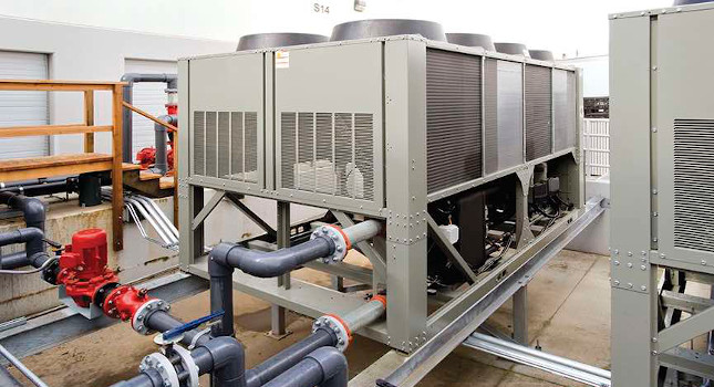
A new mission critical facility included a water-cooled chiller plant, which served all aspects of the building
A confidential project built in the southern United States demonstrates an ideal use of the water-cooled chiller plant. The project envisioned is a single-story system operations system to house the owner’s transmission control operations for the foreseeable future. The new facility is located on a wooded greenfield site.
A guiding principle for the design of the facility was to eliminate all single points of failure of critical systems. The building is storm-hardened to protect against hurricanes, tornadoes, flooding and other natural events.
The scope of certification work included design and construction of the single-free standing building and associated landscaping, drive aisles and surface parking. A portion of the site is designated for possible future expansion space, but the majority if the wooded site was preserved and enhanced, through the introduction of native grass seed at the understory of the tree canopy in the wooded area. Existing site wetlands and a pond also were preserved.
Conditioning of the noncritical, nonshielded portion of the building was done with multiple variable refrigerant flow systems. Each VRF system consists of a condensing unit (or headered-stack of condensing units), multiple refrigerant distribution devices (orientation varies with manufacturer) and multiple VRF evaporators. Each evaporator controls a zone thermostat. Pretreated outside air is ducted to each individual evaporator.
Conditioning of a loading dock area of the building is being done with a packaged direct expansion roof-top unit, unit heaters and a high-volume low-speed ceiling fan.
Outside air (ventilation) conditioning is done by a packaged DX unit. This unit consists of multiple stages of filtering, variable speed drive-driven supply and return fan arrays, an energy recovery wheel, silicon controlled rectifier electric resistance heat, ultraviolet lights, humidifier and motorized isolation dampers. The ventilation air is ducted to individual zones throughout the building using duct pressure transmitters.
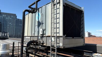
The central plant is a water-cooled chilled water system that serves all cooling equipment inside the shielded portion of the building. The system consists of redundant cooling towers, which provide condenser water to a basin. The condenser water is then pumped through a submersible pump from the basin, through a condenser water loop to a heat exchanger (condenser water supply/chilled water return), to the condenser section of each chiller. The chilled water is in a primary-secondary loop, which goes from the chiller, through the building, back through the heat exchanger and into the return side of the chiller.
Chilled water serves multiple air handling units, including underfloor air handling units, computer room air handlers and suspended fan coil units. The underfloor areas are served with thermostatic zone terminals and air supplied desks with individual thermal comfort adjusters. All heating is electric resistance. Direct digital controls are synced with a building automation system.