A data center required robust piping to transfer chilled water for cooling
A data center located in the Midwest was undergoing expansion. The project involved a new data hall with an initial load of 1,300 kilowatts and capability to scale up to an ultimate load of 2,600 kilowatts. An air-cooled chilled water plant was designed to serve the expansion space. The plant comprised of three 225-ton chillers piped in parallel to provide N+1 redundancy with the capability to add two additional 225-ton chillers in the future.
The heat transfer fluid was 40% ethylene glycol for freeze protection; each chiller featured a design flow of 380 gallons per minute and the chilled water pumping configuration was variable flow. The day one design flow was 760 gallons per minute and the ultimate design flow was 1,520 gallons per minute. Design chilled water temperature was 60 F supply and 76 F return. The system design pressure was 150 pounds per square inch gauge.
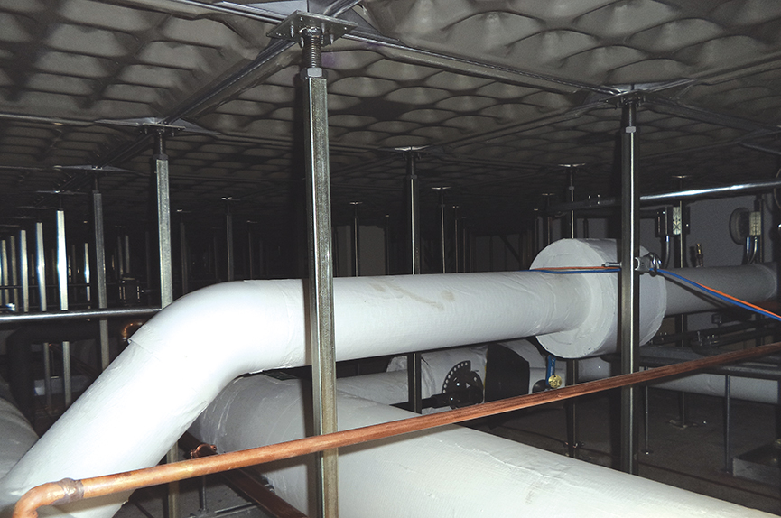
It was critical that the piping system serving the data center be robust. A piping system comprised of 8–inch schedule 40 steel pipe (ASTM A53, Grade B, Type E) with welded joints and fittings was used to create chilled water supply and return pipe loops beneath the raised access floor. The 8–inch pipe loops incorporated lugged butterfly valves at strategic locations to ensure that the piping system was concurrently maintainable — i.e., pipe segments could be isolated for maintenance activities without impacting the critical loads. Flanges were limited to valve and equipment connections. Figure 1 indicates the 8–inch chilled water supply and return loops. Also visible is 3–inch chilled water branch piping and ¾–inch condensate piping from the computer room air handling units.
The piping system above the suspended ceiling was supported from the roof structure by using clevis hangers and metal framing system was used to support the piping system on slab beneath the raised access floor. Pipe supports were provided every 10 to 12 feet in compliance with the applicable code. Additional supports were provided at heavy pipe accessories such as air separators per manufacturer requirements. Figure 2 indicates the lugged butterfly valves at the 8–inch chilled water loops and the supports for the piping system beneath the raised access floor.
Based on day one design flow of 760 gallons per minute, the maximum flow through an 8–inch pipe segment was 380 gallons per minute during normal operation, which corresponded to a pressure drop of 0.3 feet water column per 100 feet of pipe and a velocity of 2.4 feet per second. Based on ultimate design flow of 1,520 gallons per minute, the maximum flow through a pipe segment was 760 gallons per minute during normal operation, which corresponded to a pressure drop of 1 feet water column per 100 feet and a velocity of 4.9 feet per second.
In the event a pipe segment had to be isolated for maintenance during an ultimate design condition, the maximum flow through the active pipe segment was 1,520 gallons per minute, which corresponded to a pressure drop of 3.9 feet water column per 100 feet and a velocity of 9.8 feet per second. In all scenarios, the pressure drop and velocity were within the recommended limits.
Thermal expansion of the pipe system was reviewed. During normal operation, the minimum chilled water temperature was 60 F. In the event the data center was offline for an extended period and the chilled water system was disabled, the maximum water temperature was anticipated to be 95 F — i.e., the maximum temperature differential was only 35 F and the pipe loops had adequate capability to accommodate thermal stresses.
There were multiple locations where dissimilar pipe connections were necessary. For example, the CRAH units serving the data center had copper pipe connections. To reduce the potential of galvanic corrosion, dielectric flanges were used to connect steel pipe to copper.
Chlorinated polyvinyl chloride was initially considered for condensate drain piping from the CRAH units. However, few CRAH units were equipped with an integral humidifier and the units also used the condensate piping for humidifier blowdown. Due to the potential of elevated water temperature in the pipe, CPVC was deemed to be unsuitable for the application and 1–inch copper pipe (ASTM B306 Type DWV) was used per CRAH unit.
The closed–loop system incorporated expansion tanks to accommodate fluid expansion, air separator to vent air from the system, glycol feeder to fill the system with glycol solution, side-stream filter to remove suspended solids from the system and chemical feeder for periodic injection of water treatment chemicals such as biocides, scale inhibitors and corrosion inhibitors.
Pipe connections with isolation valves and blind flanges were provided to ensure that future chillers and CRAHs could be incorporated without disabling the system. Pipe dead-legs were limited to 2 feet in length.