How early stage instrumentation and controls (I&C) design decisions can directly influence system integration outcomes.
- Understand the role of controls and integration in engineering projects: Learn the fundamentals of control system design and how integration ensures that all components, instrumentation and networks work together seamlessly.
- Implement efficient design strategies to improve workflow and integration: Know some practical techniques for streamlining the control system design process, such as standardized templates, automation tools and well-structured documentation.
- Recognize how design decisions impact system integration and performance, such as instrument selection, wiring methods, network architecture and panel layouts.
Controls integration insights
- Controls integration is a critical process that begins in the earliest stages of instrumentation and controls (I&C) design, where coordination, documentation and clear communication determine system performance and project success.
- This article highlights how design-phase decisions — like defining control philosophy, standardizing signal names and planning for network and code compliance — play a pivotal role in minimizing integration challenges during construction and commissioning.
- Walk away with practical insights on better coordination, more efficient design workflows and how those early phase decisions are critical for integration success.
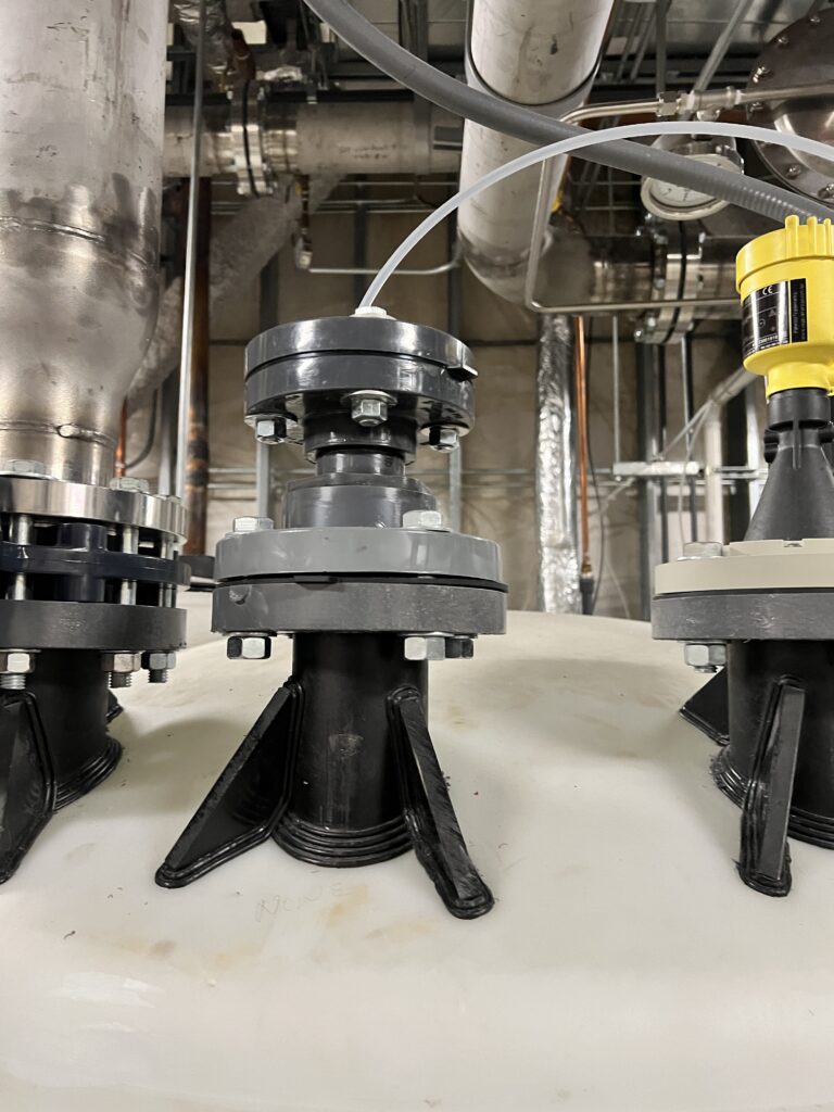
In instrumentation and controls (I&C), integration refers to the process of bringing together various control system components to function as a unified system. Components such as sensors, actuators, control panels and programmable logic controllers (PLC) all have a vital role to play in a control system and need successful integration to tie them all together.
For successful integration to occur, data needs to flow reliably between instrumentation and controllers so that the end user has full visibility and control over the entire system. Integration also comes with its challenges, which have a variety of root causes, including design. It can be easy to think of integration as something that occurs post-design during the construction phase of a project and is handled by contractors and system integrators. But over time, many of the issues that show up during integration, including conflicting signals, missing points and incompatible networks, can be attributed to gaps during the design phase of a project.
In this context, design refers to the engineering phase where the I&C team is developing control diagrams, panel layouts, schedules and drawings. These issues often stem from breakdowns in communications across engineering disciplines, vague control intent or even technical assumptions that aren’t verified until it’s too late. The early design phase plays a foundational role for how smoothly control systems can be integrated, but when these gaps are overlooked, integration problems become apparent.
I&C design touches almost every part of a building or process system, especially in complex projects like semiconductor fabs or clean manufacturing facilities. Designs interact with mechanical, electrical and process disciplines, which means coordination is critical. If all teams aren’t consistently aligned on the control intent of the system throughout the project, issues tend to arise affecting project completion.
No two projects are the same in the I&C industry. However, one common thread across every successful job is that integration isn’t something you just turn on at the end of a project: it’s the cumulative result of consistent planning, coordination and documentation from Day One.
Best practices for controls integration
There are several steps or things to accomplish when creating a strategy. Use these six tips throughout the process.
1. Start with a clear control philosophy
Every project needs a control philosophy document, often called sequences of operation (SOO). This should be kept as a living document throughout the entirety of the project. This guiding compass outlines what each system is supposed to do, what the inputs and outputs are and how different systems talk to each other.
On a chilled water plant, for example, the SOO should clearly define how chillers, pumps, valves and sensors interact. The SOO should also state and identify which system owns which control logic. For example, a building automation system (BAS) typically handles heating, ventilation and air conditioning (HVAC) equipment related controls, while a facility monitoring and controls system (FMCS) handles a more plant-wide process equipment related control scheme.
Handoffs and overlaps between controls systems should be clearly laid out in the SOO to avoid confusion. Too often, integration issues arise because this philosophy was assumed rather than documented. Without early alignment and coordination between mechanical, process and I&C teams during design to nail down the overall controls philosophy, the door opens for issues later.
2. Document control sequences and logic clearly
Control intent should be crystal clear, whether handing off a direct digital control (DDC)-based SOO or a PLC logic diagram. For example, sequences that read, pump runs when pressure is low, can be made more specific to include actual datapoints such as temperature or pressure.
Specify logic conditions, startup/shutdown conditions, failover responses and alarm states. Using function block diagrams or flowcharts to illustrate more complex sequences is good practice and can clearly convey the high-level controls intent to all parties. This doesn’t just help the integrator — it’s useful for commissioning agents, operations teams and maintenance teams long after project completion.
3. Coordinate actively across disciplines
I&C doesn’t exist in a vacuum. I&C engineers rely on mechanical engineers for equipment schedules and cut sheets, electrical engineers for power and panel coordination and process engineers for understanding operational needs. While the other disciplines provide critical input, it is important that the I&C team leads the development of control narratives, SOO’s and capturing the control philosophy on process and instrumentation diagrams (P&ID).
The best practice is to hold recurring cross-discipline design reviews specifically focused on controls throughout the design phase. Use these reviews to verify signal lists, instrumentation types, communication protocols and how different systems are being divided between packages and contractors so that all disciplines are aligned.
Standardize signal naming and documentation
Integration headaches can be avoided with consistent signal naming. Although most clients have a specification indicating the site standards, which include a naming convention for signals and instruments, if the project doesn’t have one, it is important to keep standardization in mind. Use the naming convention laid out in International Society of Automation (ISA) 5.1 whenever possible (unless using the client’s standards) and apply it across P&IDs, control narratives, input/output (I/O) lists and wiring diagrams.
When the same temperature sensor is called TS-001 in one drawing, Temp Sensor 1 in another and something else entirely in the PLC program, integration suffers. Integrators who can cross-reference everything without guessing means a job well done. It also helps reduce requests for information.
Use I/O summaries as living documents
An I/O summary table or list is more than just a checklist of field devices; it’s also a roadmap for integration. It should include tag names, signal type (analog/digital), source/destination, wire numbers and protocol type. Keep this document live and updated throughout design and share it with the integration contractor early. When using PLCs or DDC, map I/O in advance to speed up factory acceptance testing and troubleshooting.
Plan networks with IT, cybersecurity in mind
Networking is no longer an afterthought. With the rise of smart instruments and remote access requirements, planning a control network is as critical as a power single-line. Early involvement of information technology (IT), especially for projects requiring secure remote access or integration into a facility’s enterprise network, is a must. Follow cybersecurity frameworks like ISA/IEC 62443 and assign virtual LANs, internet protocol addresses and access levels early. A good I&C design also separates critical control traffic from monitoring-only devices to maintain reliability and security.
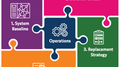
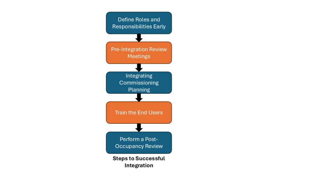
Steps to a successful controls integration project
Getting from design to a fully integrated system takes more than just a good specification. To maximize the chance of success, consider these approaches.
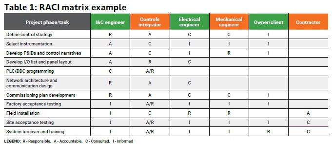
Define roles and responsibilities early: One of the most common issues is confusion over who is responsible for what, especially when multiple contractors or vendors are involved. Is the mechanical contractor providing the sensors? Is the integrator responsible for programming the variable frequency drives or is that by the vendor? Defining a matrix to identify the party responsible, accountable, consulted and informed (RACI) for controls integration can save everyone time and money.
Pre-integration review meetings: Once control drawings are 75% to 90% complete, schedule a pre-integration review that includes the I&C designer, all the engineering discipline leads, the integrator, commissioning agent and ideally the end user. Walk through P&IDs, control panels, I/O lists, network architecture and SOO. This is your last line of defense before things go into fabrication or get ordered. These meetings are often where mismatches in signal types, communication protocols or power requirements are caught.
Integrated commissioning planning: By the time construction wraps up, the I&C designer typically spends less time on site as construction observation and punch walks come to an end. That’s why it’s vital to have well-documented commissioning checklists typically developed by the commissioning party, system owner or third-party commissioning agent and a plan for how the integrator, commissioning agent and facility operator will verify control functionality. Ideally, control sequences are tested as a system, not just per device. This includes testing abnormal conditions to verify redundancy and fail-safes, like sensor failures and faults or power loss scenarios.
Train the end users: Controls may be integrated and functioning, but if the operators don’t know how to interact with the system, long-term success is compromised. Make sure part of the integration scope includes clear operator training, user manuals and standard operating procedures for basic troubleshooting. This step often gets overlooked.
Perform a post-occupancy review: Once the system has been running for a few months, it’s worth scheduling a post-occupancy review with the owner and operations team. Integration can look good on paper, but field use can uncover pain points or edge cases that could be improved with small programming or configuration tweaks. Insights gained during post-occupancy reviews can also inform design standards and streamline integration on future projects, leading to more effective and resilient systems. These reviews build trust with clients and can lead to better project outcomes.
The best integrations aren’t just about great technology, they have robust communication, planning and discipline-wide coordination. Controls integration is where the design becomes reality and if something goes wrong, it can often point back to something missed earlier in the design process. I&C engineers should anticipate those points of failure and design with the whole system in mind. The more integration can be embedded into the design, the smoother projects will run.
Codes, standards and regulations
An I&C engineer has a vital responsibility while designing systems to verify compliance with applicable codes, standards and regulations. These regulations not only ensure that a system is safe and reliable, but also that it can be integrated effectively. Ignoring or misapplying a standard poses compliance risks and can lead to rework, failed inspections and operational issues during integration and commissioning.
With that in mind, the following sections outline commonly referenced codes and standards that can have an impact and influence on the I&C design. While exact compliance requirements depend on the project type and local jurisdiction, understanding how these frameworks apply helps to ensure the delivery of a compliant system in preparation for integration.
National Electrical Code
In the United States, NFPA 70: National Electrical Code (NEC) is an essential set of codes for I&C design. While the NEC primarily governs the electrical discipline, it directly impacts how to route, protect and classify control cabling since it is common to see I&C specifications and standards derived from electrical ones.
For example, locations classified as hazardous, particularly in process or industrial environments, are covered through Articles 500 to 516 of the NEC. These articles determine what kind of rating enclosures or intrinsically safe barriers a sensor may need in various areas. This affects safety and integration. Control panel locations may need to be relocated outside of classified zones, which leads to changes in cable lengths and conduit routing. Field instruments must be selected early to ensure they meet hazardous location certifications (e.g., UL, ATEX, IECEx), as their availability and lead times may affect project timelines.
Coordination with electrical and mechanical teams becomes more complex and important, especially when devices penetrate classified boundaries or connect to systems in safe zones. Late-stage changes to any of these elements can cause cascading delays or even require redesigns. Integration planning must begin during the design phase with a clear understanding of hazardous area requirements to ensure that all systems are fully compatible and compliant.
ISA standards
ISA publishes many of the standards that govern the design and specification of control systems. One of the most referenced standards in the field is ISA 5.1, which defines symbols and identification methods used in P&IDs. This standard ensures consistent and recognizable labeling of instruments across disciplines. When P&IDs follow consistent ISA-based conventions, it reduces ambiguity and misinterpretation during integration, especially during handoffs between the design, construction and commissioning teams.
ISA standards also guide functional aspects of control systems. ISA 88 and ISA 95 are used for batch control and enterprise integration, respectively. While not every I&C designer works directly with these standards, they form the backbone of many PLC and distributed control system architectures.
On the integration side, these standards help define how plant-floor systems communicate with supervisory or enterprise systems. Failing to consider these frameworks during design may require integrators to rewrite control logic later to enable system communication.
Building codes and energy standards
Controls for HVAC systems must also comply with building energy codes, like the International Energy Conservation Code and ASHRAE Standard 90.1: Energy Standard for Buildings Except Low-Rise Residential Buildings. These mandate certain sequences of operation such as demand-controlled ventilation, occupancy-based setbacks and economizer cycles.
Any I&C design teams working on commercial and institutional buildings, specifically U.S. Green Building Council LEED or net-zero energy projects, need to be aware of these requirements and have them be reflected in their designs. Not only do these requirements affect design development, but they also tie directly into commissioning checklists and post-occupancy verification.
Standards like ASHRAE Guideline 36: High Performance Sequences of Operation for HVAC Systems provide SOO and points lists for high-performance HVAC systems, which can help to align design intent with commissioning requirements.
Capturing these codes and standards is ultimately the responsibility of the design team, as contractors and integrators will implement what is shown in the contract documents, not verify what’s missing. If the requirements aren’t accurately captured, it can delay occupancy, incur additional costs or even force redesigns during integration and commissioning.
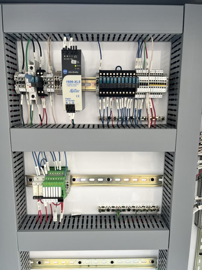
UL listings and product compliance
Another important consideration is UL product listings. Control panels, relays and instrumentation specified on projects may require a UL 508A certification. During design, it is important to select components that have a UL listing and design control panels to conform to these standards and specifications.
UL listed components are tested for safety, reliability and performance under certain conditions. Common examples of components include terminal blocks, fuses and enclosure types. It is common practice to use UL-listed parts for risk management.
Non-UL parts may cost less than their UL-listed counterparts, but risk not complying with the client’s or the authority having jurisdiction’s (AHJ) specifications and standards, which means there is a likelihood of the selected components getting rejected and causing delays. Panel fabrication or field work can be delayed if the design is not compliant.
Coordination across codes
One of the most important aspects of I&C design is navigating the overlaps between standards and codes. For example, you might have a sensor monitoring a point required for compliance with ASHRAE Standard 62.1: Ventilation for Acceptable Indoor Air Quality, but if it’s located in a classified area, then it must also meet NEC hazardous location requirements.
Similarly, a gas detection system could be designed to meet ASHRAE Standard 55: Thermal Environmental Conditions for Human Occupancy for compressed gases, but might also need to comply with ISA 60079 standards for electrical equipment in explosive environments depending on gas type and location.
In facilities involving hazardous chemicals, life safety systems or pharmaceutical manufacturing, compliance with NFPA 72: National Fire Alarm and Signaling Code is often required by the AHJ, meaning the designed gas detection system may need to be integrated into the fire alarm panel to trigger an evacuation. Adding client IT policies for networking and cybersecurity regulations like ISA/IEC 62443 further increases the risk of integration issues when standards aren’t aligned during design. A clear understanding of these codes and requirements distinguishes a feasible I&C design from a truly integrated one.
Controls integration from the very start
Controls integration starts on Day One. From the earliest stages of design, every decision made in I&C has a downstream impact on how well systems integrate during construction, commissioning and final turnover. I&C integration issues are rarely random and almost always trace back to gaps in coordination, unclear responsibilities between design disciplines and contractors or misalignment between disciplines.
By understanding and applying the right codes and standards, developing detailed I/O documentation and consistently collaborating with other engineering groups, I&C engineers can help ensure that systems function as intended, efficiently and reliably. Tools like P&IDs, I/O lists and panel schedules help bridge the gap between good design and seamless integration.
Successful integration depends on how well project needs are anticipated, design intent is communicated and handoffs are managed among all involved parties. Integration should never be an afterthought; it’s a core part of delivering safe, functional and future-ready control systems. When I&C design teams embrace that mindset early in the process, the result is a project that comes together smoothly, keeps the client happy and avoids costly surprises in the field.