Many industrial, commercial, and service businesses are sensitive to power quality problems because they affect a company’s ability to compete in a global economy.
Learning objectives
- Explain the definition of, and need for, high-quality power.
- Identify the costs related to a power quality disturbances.
- Recognize the value of gathering and interpreting data from power monitoring systems.
The generally accepted definition of clean power is “current and voltage waveforms that are purely sinusoidal.” However, this clean, or high-quality power does not have to be absolutely sinusoidal. So, what is the definition of high-quality power? Does the mere presence of harmonics on a power system indicate poor power quality? What about intermittent transients? Is that poor power quality?
Technically, there is no single accepted definition of “quality power.” Standards exist that help define criteria that can be measured, such as voltage. However, the real measure of power quality is determined by the performance and productivity of end-user equipment. If the equipment is not performing correctly, verification of proper mechanical and electrical installation and maintenance is necessary. A faulty piece of equipment, bad bearings, or poor internal connections can affect performance. If this doesn’t resolve the problem then power quality is most likely inadequate.
When we discuss power quality, what we really mean is voltage quality—because it’s the quality of the voltage that we can address. Power is the rate of delivery of energy and is proportional to the product of the voltage and current. The equipment itself—not the distribution system—defines how much power is drawn from the system. The power system defines the quality of the voltage delivered. Because there is a close relationship between voltage and current, we must address the current to understand many of the power problems that exist. For example:
- A short circuit can cause a voltage sag—or cause voltage to even disappear completely—due to extremely high current passing through the system impedance.
- Lightning generates high impulse voltages that can travel on the power distribution system.
- Distorted currents from harmonic loads also cause the voltage to distort as the current passes through the system impedance.
Sensitive electronic devices
We are heavy users of electronic devices, which are inherently sensitive to power quality. This sensitive equipment accentuates the limitations of the power system, limitations that have always existed but were rarely observed with less sophisticated equipment. Power quality issues are not easily identified. Determining how much of equipment malfunction and downtime is due to poor power quality is difficult to analyze. A power monitoring system that provides wave capture with a time stamp of the power anomaly, along with equipment status, can help facility operators correlate the cause and effect between power events and equipment malfunctions.
Since the advent of electricity, reliable, high-quality power has been desirable. In the late 1980s, computers became commonplace in our offices and homes. In the 1990s, we were able to network this equipment together to increase equipment performance. Today, we face new problems, such as faster processing speeds, increased computer chip densities, and equipment that is more sensitive to the quality of power it receives. Factories, offices, hotels, shopping centers, hospitals, and homes depend heavily on microprocessor-based loads, such as lighting controls, computers, copiers, appliances, scanners, control systems, monitoring devices, etc. It’s difficult to find equipment that lacks a microprocessor. While this electronic equipment is relatively small in size and power consumption, it is large in quantity and is in close proximity to one another.
We are interested in power quality because of its economic impact. An increasing majority of industrial, commercial, and service businesses are sensitive to power quality problems because they affect a company’s ability to compete in a global economy. Businesses that depend on high quality power, such as information technology or the continuous process industry with its programmable logic controllers, distributed control systems, industrial computers, human-machine interfaces, variable frequency drives (VFDs), motion controllers, and sensors, can suffer huge financial losses along with loss of productivity and competitiveness when power disturbances occur.
The costs related to a power quality disturbance can be categorized as direct costs, indirect costs, and inconveniences.
Direct costs: include reduced equipment efficiency, loss of raw material and production, equipment/product damage, corrupt data communications/storage, and nonproductive employee wages.
Indirect costs: more difficult to quantify and may include missed delivery deadlines, which may cause future orders to be lost.
Inconvenience: Items in this category are not expressed in lost revenue dollars but rather in how much someone is willing to pay to avoid having to deal with the inconvenience.
Ultimately, the end user is responsible for preparing appropriate performance criteria for the equipment as well as for the proper installation and correction of inadequacies in the power and grounding system. Unfortunately, many end users are unaware of the installation pitfalls and need assistance.
Many times, the local utility company can provide guidance on how to properly install sensitive electronic equipment as well as modifications to the power and grounding system. The utility is motivated to provide customer service in regard to power quality to help build and maintain confidence in its distribution system. Utility engineers can provide troubleshooting analysis of harmonic issues because of the connection requirements stipulated in IEEE 519-2014: Recommended Practice and Requirements for Harmonic Control in Electric Power Systems, which defines the maximum allowed reflective harmonics allowed from a customer. However, some specialized equipment may be beyond the abilities of the utility and may require the assistance of an engineer who is knowledgeable in power quality issues.
Having quality power is not accidental; it is well planned and carefully installed. The basics of power quality start by creating a solid foundation of grounding, bonding, and wiring; then layer on surge protection and power conditioning; and lastly, monitor power quality trends to provide a baseline for preventive maintenance activities to correct internal power quality problems and to define external power quality problems (see Figure 1).
Grounding, bonding, and wiring
Around 80% of all power quality problems are related to grounding, bonding, and wiring problems within a facility. Is this percentage exaggerated? Possibly, but many power problems are resolved simply by fixing a few grounding connections or replacing a couple of grounding cables.
Grounding and bonding are not the same. However, they are closely related. Why do we ground and bond electrical systems? The answer can be found in NFPA 70-2014: National Electrical Code (NEC), Article 250.4(A)(1) Electrical System Grounding, which states “Electrical systems that are grounded shall be connected to earth in a manner that will limit the voltage imposed by lightning, line surges, or unintentional contact with higher-voltage lines and that will stabilize the voltage to earth during normal operation.” Furthermore, grounding stabilizes the voltage to earth during normal operations for grounded systems. Electrical equipment is grounded in accordance with Article 250.4(A)(2) Grounding of Electrical Equipment, which requires that “Normally noncurrent-carrying conductive material enclosing electrical conductors or equipment, or forming part of such equipment, shall be connected to earth so as to limit the voltage to ground on these materials.”
Noncurrent-carrying conductive materials that may become energized are bonded together to establish a low-impedance ground-fault current path in accordance with NEC Article 250.4(A)(3) Bonding of Electrical Equipment, which indicates that “Normally noncurrent-carrying conductive materials enclosing electrical conductors or equipment, or forming part of such equipment, shall be connected together and to the electrical supply source in a manner that established an effective ground-fault current path.” Bonding of equipment facilitates the operation of overcurrent devices, such as fuses, circuit breakers, or relays, during fault conditions as required by NEC Article 250.4(A)(5). Multiple parallel paths result in low impedance to facilitate overcurrent device operation.
Electrical systems do not need to be grounded to function. In fact, not all electrical systems are grounded. But when discussing electrical systems, usually the voltages are with respect to ground. The term “ground” represents a reference point—or a zero potential point—to which all other voltages refer. A zero reference voltage is critical for proper operation of electronic equipment. Unfortunately, the least amount of attention is focused on grounding, bonding, and wiring. Typical wiring and grounding problems include:
- Faulty, loose, or resistive connections that result in heating, and potential arcing and burning of the insulation
- Missing equipment grounds that create situations where there is no effective return path for ground-fault current
- Power supply conduits insulated from computer cabinets with PVC conduit fittings
- Conduit runs that end before reaching the equipment with a conductor running exposed the remaining distance
- Green, insulated grounding conductors that are run separately from the phase conductors.
Another common grounding problem is using an isolated ground with the idea of obtaining a clean ground. Isolated grounds are typically misunderstood and misapplied because they are not actually isolated, but rather insulated, thereby eliminating parallel return paths. Installation of an isolated ground conductor is governed by NEC Article 250.146(D) Isolated Ground Receptacles and is used to reduce electrical noise on the grounding circuit by purposely insulating the receptacle from the mounting means. The receptacle grounding terminal is instead connected to an insulated equipment grounding conductor run with the circuit conductors, and is permitted to pass through one or more panelboards without connection to the panelboard grounding terminal bar. This isolated ground conductor terminates at the source of the separately derived system or service. The conductor is not isolated from the electrical grounding system.
Sometimes isolated or dedicated grounds are recommended by equipment manufacturers. These recommendations can compromise the safety and performance of the equipment, are dangerous, violate the NEC, and are unlikely to solve power quality problems.
Safety and equipment performance depend on the proper selection and installation of the power and electronic equipment grounding and bonding system. In all circumstances, the equipment and grounding system must comply with the NEC and local installation codes. A solidly grounded ac system with insulated equipment grounding conductors should be used to feed electronic loads. All metal parts of equipment enclosures, raceways, and grounding conductors are to be effectively and permanently bonded to each other and to the power system grounding electrode system at the service entrance and at each separately derived system.
There are several different types of high-frequency noise that must also be addressed when discussing grounding, which include:
- Normal mode noise, which is the noise between the phase and neutral conductors.
- Common mode noise, which is the noise between the phase conductor and ground.
- Electromagnetic interference or radio frequency interference can be radiated or conducted along power or data lines. This noise can come from automobile ignition systems, radios, or electrical power transmission lines. These types of high-frequency noise can also accompany high-voltage surges traveling along power lines.
To prevent high-frequency electrical noise from affecting sensitive equipment, it may be necessary to install a signal reference grid (SRG). According to IEEE 1100-2005: Recommended Practice for Powering and Grounding Electronic Equipment, an SRG provides grounding for high-frequency electrical noise over a broad range of frequencies by creating an equipotential ground plane consisting of a mass of conducting material bonded together to provide a uniformly low impedance to current flow. This is a separate system from the NEC-required power system grounding. Both systems must be bonded together. An SRG system is not related to the power system grounding, and the SRG will work whether or not it is grounded to the power system ground. In fact, there is no conflict between safe grounding for people and effective high-frequency grounding for electrical systems (see Figure 2).
Improper wiring can cause power quality problems. Multiple neutral-to-ground bonds create parallel return paths, causing fault current to split between ground and neutral. Another common wiring issue is insufficiently sized neutral conductors that can’t handle the harmonic content of the load. Note that third-harmonic currents from separate single-phase loads are added in the neutral conductor instead of canceling each other out. Panels and branch circuits that serve electronic loads should have larger neutral busses and conductors to handle these increased neutral currents.
Many harmonic problems associated with power systems are typically caused by equipment located within the facility itself. The effects of these internal harmonic-producing sources can be mitigated at the source with appropriately engineered designs that include input line reactors on VFDs, filters on uninterruptible power supplies (UPSs), and harmonic mitigating transformers. Raceways and conductors should be installed in a manner that keeps the lengths as short as possible to reduce system impedances. Items such as lighting ballasts can be specified with requirements that limit the total harmonic distortion voltage. Installations should be designed so that harmonic-producing loads are segregated from sensitive building loads, thereby reducing load interaction. Not all harmonic-producing equipment needs the same level of protection. Therefore, the solution should be appropriate for the source. Providing protection that’s better than required is costly and unnecessary.
Surge protection
According to the National Institute of Standards and Technology publication SP-768, power disturbances fall into two categories: steady state and intermittent. Steady-state disturbances are noise, harmonics, and long-term undervoltages and overvoltages lasting more than a few seconds. Surges are different from noise in that a surge is of short duration and a non-steady-state intermittent transient lasting several cycles. The boundary between the two is not completely clear, and different groups of engineers can have varying opinions on this boundary. Surges caused by lightning are a result of either a direct strike to the power system, or an induction of overvoltages in loops formed by the conductors and ground potential increases caused by the lightning. The induction of surges by lightning discharges is more frequent than direct strikes.
Load switching can also cause surges. Whenever capacitive and/or inductive loads are switched (either on or off), the currents and voltages do not respond instantaneously. The severity of the surge depends on the size of load being switched and on the available short-circuit current, or robustness, of the power system in which the switching takes place. Electrostatic discharge is another well-known cause of surges and is capable of damaging sensitive electronic components. However, this type of surge is quickly attenuated in power systems due to the high frequencies of the surge and the distances of the power cables.
A lightning risk assessment based on NFPA 780: Standard for the Installation of Lightning Protection Systems, Annex L, is a good way to determine if a facility should have lightning protection, and, if required, the protection should be installed in accordance with this standard. To properly deal with the surge energy associated with lightning strikes, surge suppression devices (SPDs) should be installed on the power system. SPDs do not absorb the energy. Instead, they divert the surge to ground. SPDs do not correct sags, swells, harmonics, or other voltage conditions. IEEE Standard C62.41-2002: Recommended Practice on Characterization of Surges in Low-Voltage (1,000 V and less) ac Power Circuits defines three categories of SPDs. Starting from the load, Category A SPDs are installed on outlets and long branch circuits. Category B SPDs are installed on main feeders and short branch circuits. Category C SPDs are installed outside and at the service entrance. All exterior mechanical systems, such as cooling towers, fans, and pumps, should have Category B or C SPD protection as well as any metallic items, such as conduit, that may pass in and out of the building (see Figure 3). In going from Category C to Category A, the transient voltage and current levels become progressively smaller because of the inherent impedance of the power distribution system. Unfortunately, IEEE C62.41 defines SPDs slightly differently than NEC Article 285 Surge-Protective Devices (SPDs), 1,000 V or Less. According to Article 285, there are three types of SPDs: Type 1, Type 2, and Type 3. The IEEE categories and the NEC types align as follows:
- Category A aligns with Type 3 per Article 285.25.
- Category B aligns with Type 2 per Article 285.24.
- Category C aligns with Type 1 per Article 285.23.
For systems rated higher than 1,000 V, surge arresters should be installed, not SPDs. Surge arresters are installed in accordance with NEC Article 280: Surge Arresters over 1,000 V.
It’s important to note that burying conductors outside does not make them immune to the effects of lightning surges. Underground conductors are just as susceptible as overhead conductors to lightning surges and must be protected.
Surges from lightning or switching may also impact data communication cabling. The recommended practice is to contain the data cables in properly grounded metallic conduit. Additionally, the data communication cabling (not fiber optic) should also be protected by an appropriate SPD.
Power conditioning
There are many products that can condition power to meet the needs of sensitive electronic loads. Typically, there are two types of power conditioning equipment: power enhancement and power synthesis. Power enhancement equipment only improves the waveform by filtering, isolating, clipping, and increasing or decreasing the voltage. Power enhancement equipment includes ferroresonant, electronic tap-switching, and shielded isolation transformers.
Power synthesis equipment uses the incoming power waveform to create a new, isolated power output waveform. Power synthesis equipment includes static UPSs, rotary UPSs, and motor-generator sets.
Determining which type of power conditioning equipment to use depends on the quality of the incoming power and the effectiveness of each type of system to solve those problems, as well as the performance requirements of the electronic equipment. In most instances, the electronic equipment will conform to the Information Technology Industry Council (ITIC) standards. However, some equipment may have higher power quality standards.
The ITIC curve is a guideline for voltage susceptibility of electronic equipment. Originally, this curve was known as the Computer and Business Equipment Manufacturers’ Association (CBEMA) curve. However, in the mid-1990s, CBEMA was reorganized and renamed to Information Technology Industry. ITI modified the CBEMA curve and it is now known as the ITIC curve (see Figure 4).
If the incoming voltage falls between the two curves, then it is acceptable. If the voltage falls below the bottom curve or exceeds the limits of the top of the curve, the electronic equipment will likely fail to perform.
The curve was developed primarily for 120 V computer equipment, but it has been generally applied to most other types of electronic equipment. However, the ITIC curve is not intended to define the performance of all electronic equipment. It is a general guideline, and specific power quality requirements should be obtained from equipment manufacturers.
Power quality monitoring
To correct problems that can affect electronic equipment, it is necessary to identify the source of the problem using a monitoring system. Technology and software are available that allow early detection of problems within the distribution system before equipment malfunctions and failures.
Power quality monitoring can assist in preventive and predictive maintenance by identifying the source and determining the frequency of problems, in addition to establishing the precise location and timing of events, thereby allowing maintenance activities to be scheduled. Monitoring helps determine if there is a need for mitigating equipment to correct harmonics, voltage sags or swells, or transients, or if power conditioning equipment is necessary. Additionally, monitoring equipment can be used to benchmark overall system performance to ensure that existing equipment is operating within acceptable parameters.
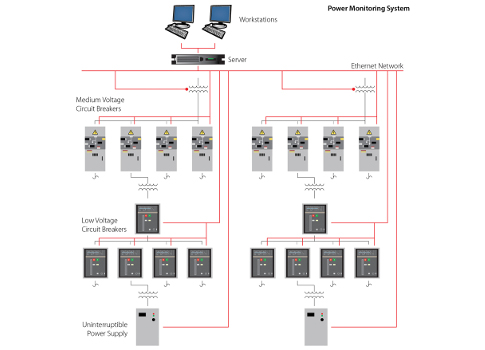
The extent to which a power monitoring system is deployed throughout a facility depends on the need for improving (or maintaining) power quality performance. Some facilities have extensive power monitoring systems while others have simple systems. Many options are available that can provide historical trends, harmonic analysis, and intelligent systems (see Figure 5).
Consult guidelines and standards
Design practices and installation standards for preventing power quality problems are extensive and can, at times, seem confusing and conflicting. This article focuses on power quality basics. However, the field of power quality is quite large. There are many recommended guidelines and standards for engineers and installers to follow in developing a system that limits the effects of power quality problems. But, at no time should a recommended practice take precedence over a national or local installation code. There is no single solution to all power quality problems.
The following standards are highly recommended for anyone wanting to learn more about power quality for electronic equipment:
- IEEE 519: IEEE Recommended Practice and Requirements for Harmonic Control In Electric Power Systems
- IEEE 1100: IEEE Recommended Practice for the Powering and Grounding Electronic Equipment (Emerald Book)
- IEEE 1159: IEEE Recommended Practice for Monitoring Electrical Power Quality
- IEEE C62.41: IEEE Recommended Practice for Surge Voltages in Low-Voltage ac Power Circuits
- NFPA 70: National Electrical Code
- NFPA 75: Standard for the Fire Protection of Information Technology Equipment
- NFPA 780: Standard for the Installation of Lightning Protection Systems.
Debra Vieira is a senior electrical engineer at CH2M. She specializes in data center and mission critical environments.