Electrical engineers have several items to consider when interconnecting renewable energy production systems.

Learning objectives:
- Explain the basics of connecting a renewable energy production system (REPS) to a building’s electrical system.
- Help system designers, integrators, and owners consider the implications of different interconnection options and requirements for utility interactive REPS.
Whether designing a renewable energy production system (REPS) to connect into an existing building’s electrical system, or designing a solar-ready facility where only a means to interconnect a future REPS is provided, the details of the interconnection can have a major impact on the design, cost, and schedule of a REPS project.
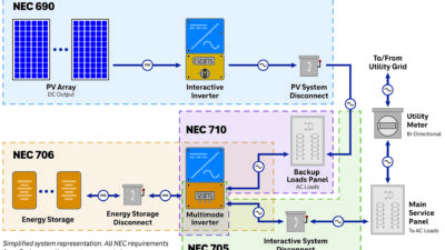
The design of an electrical utility grid-connected REPS, whether it be photovoltaic (PV), wind, or alternative technology, can be broken into two parts:
- The energy system itself, including production equipment, conversion equipment, and any other balance of system components
- The electrical interconnection to the grid.
The design of the former is usually straightforward, and the rough cost and design is easily predicted as early as the proposal process. The interconnection design, which is often overlooked until later in the design process, can have drastic implications on the system size, project schedule, and project costs—both the upfront cost and lifecycle cost of the system. Considering the electrical interconnection early will improve the likelihood of eliminating project pitfalls associated with these items.
The major factors influencing the interconnection design are code requirements, utility requirements, owner requirements, and existing equipment conditions. These factors are discussed in detail in regards to their impact on the overall REPS design. For the sake of this article, all REPS are assumed to use utility interactive inverters, thus fall under the requirements for those types of inverters.
Code requirements
NFPA 70: National Electric Code (NEC) Article 705 provides requirements for interconnecting REPS. Article 710.12 addresses the point of interconnection and offers three possibilities. Each of these possibilities presents different benefits and restrictions, and each can affect the maximum system size allowed, the cost of the interconnection, and other system parameters. The interconnection possibilities are presented in the order in which they are likely assessed during design.
NEC 705.12(D)(2)—load-side interconnection: The most common type of interconnection for smaller-scale REPS is a load-side interconnection, commonly known as a load-side tap. The general rule for this type is that the interconnection overcurrent protection (OCP) must be placed at the opposite end of the busbar from the main OCP, and that the sum of the main OCP and the interconnection OCP cannot exceed 120% of the bus rating (see Figure 2). For smaller REPS, this option is often chosen because it is relatively inexpensive, uses spare capacity within existing equipment, and is well-understood by the authority having jurisdiction (AHJ) and electric utilities. For larger REPS, however, this option may present a challenge as the 120% rule limits the OCP for the REPS and, therefore, the size of the REPS.
To increase the potential size of the REPS with a load-side tap, either the busbar size must be increased or the main OCP must be decreased. For existing buildings, increasing the busbar size is unlikely to be a cost-effective option. It is also uncommon for the main OCP to have a lower rating than the busbar. However, it is likely that the peak demand on the existing equipment will be substantially less than the OCP rating. If metering the main OCP shows that this is the case, the main OCP may be reduced (either replaced or, if an electronic trip unit is present, dialed down) to allow for a larger REPS to be connected on the load side (see Figure 3). If a main OCP reduction is desired, the implications of the resulting reduced system capacity should be discussed with the owner. If a main OCP reduction is not possible, an alternate method must be considered.
NEC 705.12(A)—supply-side interconnection: This article allows the REPS to be interconnected ahead of the main disconnecting means for the site. This option, usually referred to as a supply-side tap or a line-side tap, allows for output amperage of the REPS to be as large as the busbar rating.
The big question that usually arises for this interconnection is, "Where exactly do we make the tap?" For a new system, the answer is easy. A tap location ahead of the main OCP can be provided in the gear in a similar fashion as a fire pump would be connected (see Figure 4). The REPS OCP could be an externally fused disconnect or a breaker/disconnect integrated into the switchgear.
For existing installations, this option can be tricky. Adding a breaker or tap section to an existing piece of gear will likely be costly, as it would require significant modification of the equipment. This leaves tapping the busbar somewhere ahead of the main OCP but after the utility meter (see Figure 5). With the many different gear configurations out there, this may or may not be possible. To find out, a few parties will need to be involved.
To evaluate a line-side tap, it is recommended to first get the gear identification number, usually located on a sticker on the front of the gear. With this, you can contact the manufacturer and find out, based on the shop drawings, whether a tap can be made ahead of the main without voiding the UL listing of the gear. The manufacturer may affirm it is possible, and even be able to provide you with a part number for a tap kit. If the board contains multiple metering sections, the manufacturer may say it is possible within one of the metering sections, in which case you would need to contact the utility and get permission to tap in one of their unused sections.
If the manufacturer replies that it is not possible without voiding the UL listing, you have one more option. You can contact a field-listing agency to evaluate a line-side tap and relist the gear if required. This will require two site visits by the agency. The first trip will involve the agency taking measurements in the switchgear to ensure proper clearances. Upon completion, the agency will then confirm whether a line-side tap is feasible. If feasible, they will indicate how it is to be done, and they will need to come back after the installation is complete to inspect the gear and relist. This process does carry a price tag; however, in most cases it will be cheaper than providing a new switchgear line-up placed ahead of the main switchgear to tie-in the REPS and refeed the existing switchgear. In some locations, the utility may allow you to move the utility meter and tie-in the REPS at the secondary of the transformer.
NEC 705.12(C)—greater than 100 kW: If the REPS is greater than 100 kW or the service is more than 1,000 Vac, the design is not restricted by the previous two options assuming you qualify with two additional requirements:
- Only qualified persons may service and operate the equipment.
- Safeguards, procedures, and protective equipment are established and maintained.
As a rule of thumb, this type of interconnection is dedicated for locations with a permanent electrical staff that maintains the equipment. In most cases, this option takes form as a load-side tap that exceeds the 120% rule.
Utility requirements
Utility requirements vary significantly between different utilities. They represent another layer of complexity that comes with the interconnection design. Generally, utilities will allow any of the previously mentioned interconnection methods, but will have additional requirements beyond the NEC. The utility may enforce:
- Disconnect requirements. The utility may require a dedicated disconnect for the REPS. The disconnect may require a viewing window, and it may be required to be in a certain area.
- Net metering. If the installation is in a location that does not allow net metering, then the REPS will not be allowed to back-feed the utility. In this case, a reverse power relay will need to be included in the interconnection design. Depending on the proximity of the current transformers to the inverters or controls, additional infrastructure for data/communication wiring may be needed.
- Transformer winding configurations, such as wye-wye, if a transformer is required for interconnection.
- Grounding requirements for the REPS that cannot be met without the addition of a grounding transformer.
- An interconnection study (if the size of the REPS is large enough) to study steady-state and transient behavior of the local grid.
To understand what requirements apply to you, it is recommended to talk with the utility or read through the interconnection documentation if it’s available.
Owner requirements
Many facilities have only one service, leaving no question about which services are available for interconnection. Large facilities may have multiple services of different sizes. The variety of sizes may result in a variety of utility rate schedules. If this is the case, it may be more financially beneficial over the lifetime of the REPS to interconnect with one service over another.
Existing gear age and condition
Occasionally, the path to interconnection may involve switchgear that does not appear to be in safe working order or consists of obsolete components. In these instances, a conversation with the building owner should take place. If replacing the gear is feasible, it may be something the owner will pay for. If not, new switchgear placed between the utility meter and the main switchgear may need to be provided.
Solar-ready or net zero ready recommendations
The process for evaluating and determining an interconnection of a REPS of a known size has been recommended above. But what if the system size is not known? If designing a solar-ready or net zero ready building in which the size of the REPS is likely unknown, another strategy may be used. The most flexible option for future interconnection is always a line-side tap. A breaker, fused disconnect, or provision for either located ahead of the main OCP and of the same amperage as the main OCP will allow for interconnection of the largest possible REPS. However, the largest possible REPS may be physically larger than the site can accommodate, and a line-side tap may be more expensive than a load-side tap. Therefore, it is helpful to evaluate a few potential sizes and their associated interconnection requirements.
For example, assuming the REPS is PV, some suggested system sizes to study include:
- Small—enough PV to cover unused roof space
- Medium—enough PV to cover the roof and parking areas via covered parking structures
- Large—enough PV to offset 100% of the annual electrical usage of the building. (Note: if the building uses gas, it will likely not be possible to offset 100% of the total energy. This scenario would require the building to be a net producer of electricity, and the building will not fall under net meter requirements.)
If the number of PV modules needed for the large system would cover the entire site, it seems improbable that a system of this size will ever be installed. If the medium system could tie-in via load-side tap and would be cheaper in the long run, then a load-side tap may be chosen over the line-side tap.
In summary, the design for interconnection of the REPS can be more involved than the design of the REPS itself, and can have greater impacts on the project cost and schedule. The earlier in the process the information can be gathered to steer the interconnection design, the less likely you are to experience pitfalls and surprises later on. It is important to consider the interconnection design and process whether bidding design work or installation.
If a project involves architectural design, it is beneficial to all involved—architects, engineers, and owners—for the renewable energy and architectural-design processes to be integrated. If the architecture needs are designed with the design of the renewable energy system in mind, the system designers will be able to integrate their system as a function of the final product, as opposed to an after-the-fact addition. As the demand for renewable energy design continues to grow, having architectural designers and facility owners who understand the operation of these systems will be imperative.
Sean Avery is an electrical engineer and senior associate at DLR Group. His recent work includes Fortune 500 energy provider NRG to design large photovoltaic arrays at the MGM Mandalay Bay in Las Vegas as well as professional football at the stadiums of the New England Patriots, Philadelphia Eagles, San Francisco 49ers, and Washington Redskins.