Power electronics can increase energy savings, and at the same time can distort the quality of electrical power. Here are some tips to mitigate harmonics.
While power electronics have created considerable energy savings, they can distort the quality of electrical power delivered through the building they serve, reducing the effectiveness and life span of the power electronics contained within that building.
This article focuses on the largest share of power electronic loads in today’s buildings, variable frequency drives (VFDs), which are a form of power electronics used to vary the speed of the motor they serve. Globally speaking, motors account for more than two-thirds of electricity consumed by the industrial sector, and also for nearly 40% of all electricity consumed by commercial buildings. This is significant when one considers that 75% of motor applications are variable torque fan, pump, and compressor loads (common to HVAC applications) that can greatly benefit in reducing energy consumption by employing VFDs.
There is much room for improvement in how efficiently ac motors are driven: it’s estimated that as of 2011, only 3% of the total base of installed ac motors use VFDs.
This article covers the following:
- A primer on electrical harmonics and their negative effects on the building electrical system
- How the VFD creates harmonics
- IEEE 519 guidelines for the reduction of electrical harmonics
- Several design techniques for mitigating harmonics with recommended applications.
Harmonics and negative effects
In North America ac power is based on a continuously varying voltage and current waveform that follows a pure sinusoid of a frequency of 60 Hz. Harmonics are voltage and current waveforms that are sinusoids with frequencies that are multiples of the base frequency signal, called a fundamental. For example, a 3rd order harmonic of a 60 Hz fundamental has a frequency of 180 Hz. When their waveform is added to the fundamental waveform, harmonics distort the shape of the voltage and current from that of a pure sinusoid.
Pure sinusoidal voltage is a concept based on an ideal ac generator with a finely distributed stator and evenly distributed field windings that operate in a uniform magnetic field. Because such an ideal does not exist even with the best of well-built generating plants, voltage distortion on the order of 1% to 2% does exist even where building loads generating harmonics have been eliminated.
Most harmonics in electrical systems are contributed by nonlinear loads—defined as loads with varying impedance—where current flow is not in direct proportion to the voltage applied. The most common examples of nonlinear loads in present-day electrical systems are intermediary power supplies that use electronic switching to convert building 60 Hz ac voltage into a form usable by the downstream load.
The result of this varying load impedance becomes apparent when comparing the profile of the electrical current in relation to the applied sinusoidal voltage input. The resulting current appears in a nonsinusoidal pattern, imposing multiple frequencies within the normal 60 (or 50) Hz sine wave. These multiple frequencies are harmonics of the fundamental frequency.
Examples of nonlinear loads include a variety of electronic loads such as battery chargers, switched mode power supplies (SMPS), UPSs, personal computers, electronic ballasts, LED drivers, and VFDs. Due to their relatively large size compared to other electronic loads within a commercial or industrial building, VFDs typically create the greatest distortion to current flow and building voltage.
With most common 3-phase electronic power supplies, 5th and 7th harmonics on the input current are common, and can chop up a sinusoidal current signal until it only vaguely resembles its normal pattern (see Figure 2).
While troublesome in their own right, harmonic currents drawn by nonlinear loads result in still greater problems when the voltage drop they cause over electrical conductors results in harmonics in the voltage seen by all or some of the building electrical system loads, which in turn generates harmonic currents being delivered to even linear loads.
The resulting harmonics in the building voltage can have several detrimental effects on connected electrical equipment:
- Conductors: overheating and energy losses due to the skin effect, where higher frequency currents are forced to travel through a smaller cross-sectional area of the conductor, bunched toward the surface of the conductor.
- Transformers: higher eddy current losses due to higher frequency currents circulating in the transformer core.
- Motors: higher iron and eddy current losses; mechanical oscillations induced by current harmonics into the motor shaft can cause premature failure and increased audible noise during operation.
- Other VFDs and electronic power supplies: distortion to building voltage waveform can cause failure of commutation circuits in dc drives and ac drives with silicon controlled rectifiers (SCRs).
Finally, on a building-wide basis, the sum of all of the above energy losses results in higher electricity bills. Higher electrical currents to produce the same amount of work produce greater resistive losses in the electrical system.
How VFDs work and create harmonics
VFDs create a considerable amount of energy savings, especially in variable-torque centrifugal fan and pump applications, where loads’ torque and power vary with the square and cube, respectively, of the motor speed. For example, at 63% of full speed a 3-phase motor consumes only 25% of its full speed power.
A VFD controls the speed of a motor, from no movement at all to its rated output. For fans and pumps, with their square-law or cube-law power characteristics, running at something less than full speed can dramatically reduce energy consumption when the systems don’t require the full motor output.
A VFD system generally consists of an ac motor, a controller, and an operator interface. We will review the motor and controller.
Motor: The motor is typically a 3-phase induction (“squirrel cage”) motor. Motors used with VFDs are typically designed for “definite purpose inverter fed duty” in accordance with Part 31 of NEMA Standard MG-1.
Controller: The VFD controller is a solid state power electronic conversion system consisting of three sub-systems (see Figure 3): a rectifier bridge converter, a dc link, and an inverter. Variable source inverter (VSI) drives are by far the most common, and typically convert ac line input to ac inverter output. Below we describe the most common VFD in commercial building applications, the 6-pulse VFD:
- Rectifier: Typically a 3-phase, 6-pulse, full-wave diode bridge. This device converts the ac power of the building into dc power. Because diodes allow current to pass one way (toward the motor), electrical energy does not flow back from the motor to the power system.
- dc link: Inductor/capacitor pair that levels the converter’s dc output ripple and provides a stable voltage to the inverter even when building voltage can vary.
- Inverter: Six insulated gate bi-polar transistors (IGBTs) that switch at high frequency (typically 8 kHz or higher) using a technique known as pulse width modulation (PWM) to create a 3-phase variable ac voltage/frequency output to the motor in the form of a stepped quasi-sinusoidal ac voltage output. Variable torque applications (such as fans and pumps) use a volts per Hertz (V/Hz) drive control, with voltage output of the inverter adjusted to match the required load torque in linear V/Hz relationship.
The building electrical system only sees the first stage of the VFD, the 6-pulse rectifier, as the connected load. When connected to the sinusoidal voltage source of the building power, the rectifier will produce two nonlinear current pulses during each half-wave of ac voltage (see Figure 4). The rectifier produces harmonics of the 5th, 7th, 11th, 13th, etc., orders of decreasing amplitude as order number increases.
When do harmonics become a problem in electrical systems? Problems from electrical harmonics mentioned above tend to appear when two conditions are met:
- Percentage of nonlinear loads to total electrical load in a building is relatively high.
- The “stiffness” (or source impedance of the building power supply) is also relatively high, resulting in greater voltage distortion from the same amount of harmonic current flow.
This raises the questions: How much harmonic content is considered relatively high? and How much source impedance is considered relatively high.
IEEE 519-1992
As mentioned above, harmonics in current flow can affect other electrical loads by distorting the sinusoidal waveform of the voltage source seen by all connected loads. Looking further upstream in the electrical power network, distortion of the voltage supplied by a power utility means that multiple customers can be affected by harmonic current injected into the power network by each customer, affecting the efficiency, reliability, and even safety of their power systems.
IEEE 519-1992, IEEE Recommended Practices and Requirements for Harmonic Control in Power Systems, was written in part by the IEEE Power Engineering Society to help define the limits on what harmonics will appear in the voltage the utility supplies to its customers, and the limits on harmonics that will appear in current that customer loads draw from the utility. While the standard focuses mainly on industrial customers, the source of the largest concentrations of nonlinear loads, the same standards apply to commercial customers.
To best understand the standard, three key terms need to be explained:
Point of common coupling (PCC): As specified in the IEEE 519-1992, this is the point where the utility-owned electrical system and the customer’s system are connected together, typically at the facility’s main electrical panel or at the utility meter. An important point to remember here is that the utility sees the sum of the consumer’s loads at the PCC. The distortion of the collective load as seen at the PCC is typically much better than the distortion seen at any one individual nonlinear load, and filtering methods employed downstream of the PCC can improve the harmonic current flow seen by the utility at the PCC.
Total harmonic distortion (THD): THD is described as the instantaneous value of the ratio of the root-mean-square (rms) of the harmonic content to the rms value of the fundamental quality, as expressed as a percentage of the fundamental. This can apply to either current or voltage.
Total demand distortion (TDD): TDD uses a similar formula as THD, except that the values used for current or voltage are based on a sliding average seen over a 15- or 30-minute window of time, and so gives a less biased picture of the overall harmonic problem.
Now with these three terms defined, we can explain two important tables from IEEE 519-1992, and their application to VFDs. First, in IEEE 519-1992 Table 10.3, we see that the maximum allowable current THD is based on the ratio of available fault current at the PCC compared to measured peak demand load (Isc/I in the first column). In other words, more harmonic content is permissible at a service with a lower source impedance (higher available fault current) than at one with a higher source impedance (lower available fault current).
Table 1: From IEEE 519-1992, permissible THD levels decrease as the ratio of available fault current to peak load current (Isc/I) decreases Courtesy: IEEE
IEEE Table 10.3: Current Distortion Limits for General Distribution Systems (120 V to 69 kV)
|
|
Max permissible current THD (h=harmonic order # for odd harmonics) in % |
|||||
|
Isc/I |
<11 |
11<=h<=17 |
17<=h<=23 |
23<=h<=35 |
35<=h |
TDD |
|
<20 |
4.0 |
2.0 |
1.5 |
0.6 |
0.3 |
5.0 |
|
20 to 50 |
7.0 |
3.5 |
2.5 |
1.0 |
0.5 |
8.0 |
|
50 to 100 |
10.0 |
4.5 |
4.0 |
1.5 |
0.7 |
12.0 |
|
100 to 1000 |
12.0 |
5.5 |
5.0 |
2.0 |
1.0 |
15.0 |
|
>1000 |
15.0 |
7.0 |
6.0 |
2.5 |
1.4 |
20.0 |
|
Note 1: Even harmonics are limited to 25% of odd harmonic limits above. |
||||||
|
Note 2: Current distortions resulting in a dc offset are not allowed. |
||||||
|
Note 3: Isc/I is defined as ratio between available fault current and maximum demand load |
||||||
|
current (fundamental frequency component) at the PCC. |
||||||
For most commercial buildings, utility transformers will have an impedance of around 5%, resulting in a ratio of Isc/I of 20, which then results in a target TDD value of 8.0. Since large harmonic sources in commercial buildings are concentrated at locations with many VFDs (mechanical rooms, elevator banks, chillers), harmonic reduction techniques can be applied at the portion of the electrical system serving these loads, which in turn reduces the measured TDD seen upstream at the PCC.
IEEE 519-1992 Table 11.1 indicates how acceptable voltage distortion levels are considerably lower than allowable harmonic current draw levels because a smaller level of harmonic distortion in the voltage signal can be seen by all nearby connected loads, linear and nonlinear, increasing the amount of harmonic current they each draw.
IEEE Table 11.1 Voltage distortion limits
|
Bus Voltage at PCC |
Individual Voltage Distortion % (TDD) |
|
69kV and below |
3.0 |
|
69kV to 161kV |
1.5 |
|
Above 161kV |
1.0 |
Harmonic reduction approaches
As noted earlier, most VFDs switch power to a motor load using a 6-pulse rectifier. Due to their relatively lower cost, 6-pulse rectifiers are typically used for most pulse-width-modulated VFDs sold today.
Drive performance can be improved with decreased harmonics and higher efficiency (and power factor) through a variety of means:
Input line reactor: An inductor in series with the rectifier, this is the most common solution due to its small size and cost. It reduces harmonics at the VFD because its impedance at harmonic frequencies is higher than at the fundamental frequency. Line reactors are typically built into the VFD at its input, and come in standard impedance ranges of 1.5%, 3%, 5%, and 7.5%. A choice of 5% is typically picked as a compromise between harmonic filtering, cost, and load efficiency.
Isolation transformer: Because transformers are inductive loads in their own right, they also can reduce higher frequency currents (much like input line reactors). In certain cases they can provide a relatively inexpensive reduction to harmonic levels compared to the approaches listed below, especially when one transformer serves multiple VFDs.
12-pulse rectifier VFD: For much larger motor loads (over 50 hp), this rectifier version is sometimes used to eliminate the more common 5th and 7th harmonics. In this case, the front end of a bridge rectifier uses a phase shifting power transformer and 12 diodes rather than 6 diodes alone (see Figure 5). This has the advantage of cancelling the 5th and 7th harmonics, leaving the 11 and 13th harmonics as prevalent, though typically at a much lower absolute magnitude. Disadvantages in this approach are cost and larger physical size of the installation, which requires space for a delta-delta and a delta-wye transformer, a “zig zag” transformer, or autotransformer to accomplish a 30-deg. phase shift needed for proper operation. Also, losses in the transformers lead to a lower overall efficiency and higher drive losses.
Delta-delta and delta-wye transformers: This configuration uses two separate utility-fed transformers serving roughly equal nonlinear loads. The net result is two separate power systems, with a 30-deg. phase shift between them. The harmonic loads of each system are summed at the PCC, and to a large extent, the harmonics cancel out one another. This is analogous to using the solution of the transformers of the 12-pulse rectifier VFD over multiple VFDs, much like the isolation transformer solution mentioned above.
Harmonic trap filters: These are used in applications where there are significant harmonics (with regard to the IEEE 519-1992 recommendation), and using a single filter upstream of many nonlinear loads may be more cost effective compared to other approaches. Such filters are typically tuned to largely eliminate one or more specific harmonics such as 5th, 7th, or 11th. They can be designed for several nonlinear loads or a specific individual load. They also make excellent retrofit solutions (see Figure 5). Because such filters make extensive use of capacitors, they have the problem of causing leading power factor when lightly loaded.
Active front end (AFE): A bi-directional IGBT switching device bridge used as the VFD’s rectifier instead of a silicon-controlled rectifier (SCR). An AFE input current waveform can be nearly sinusoidal. They are the most expensive of all options for a single load, but can potentially be the best means of reducing harmonics for very large motor loads (over 50hp).
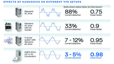
A summary of the relative impact of these solutions, including their effect on power factor and current THD percentage is given in Table 2. Courtesy: Schneider Electric:, “Data Bulletin: Reduced Harmonics Technology in Altivar 212 Adjustable Speed Drives,” July 2011
Table 2: Drive harmonic performance versus cost
|
Drive topology |
Total harmonic distortion (THD) |
Cost ratio |
|
VFD (6-pulse) |
>80% |
1.0 |
|
VFD with 5% impedance input filter |
<40% |
1.05 to 1.15 |
|
VFD with broadband passive filter |
5% to 12% |
1.35 to 1.70 |
|
VFD with multi-pulse rectifier (12, 18-pulse) |
5% to 12% |
1.75 to 2.50 |
|
VFD with AFE |
<5% |
2.00 to 3.00 |
Application
In most cases the simplest approaches, such as the use of the line reactors, can reduce harmonics enough at each VFD to lower harmonics at the point of connection to the utility to below levels required by IEEE 519-1992 for proper operation of connected electrical equipment.
However, the use of harmonic filters can act as insurance to prevent centralized sources of harmonics in buildings, such as elevator banks or mechanical rooms, from becoming a source of trouble for future electronic loads. Active and passive harmonic filters that are connected in parallel with VFD loads can serve as harmonic “sinks,” and can work well in retrofit applications provided the space is available for their installation.
Decreasing cost of AFE VFDs suggest they may become an increasingly feasible solution in the future, especially for larger motor loads, where their physical size difference is minimal compared to older solutions such as the 12-pulse rectifier.
VFDs will continue to grow in prevalence as their costs continue to decline, and more facility managers become comfortable with their applications in boosting HVAC system efficiency and lowering energy bills. Planning and managing the more hidden concern of electrical system harmonics ensures that building managers will continue to reap those benefits without inadvertently decreasing the reliability of the electrical power to all electronic loads.
David Chesley is associate principal/senior electrical engineer at Interface Engineering. His expertise includes building integration, renewable energy systems, telecommunications infrastructure, backup power systems, VFDs, and energy metering and building dashboards.