Anatomy of a Central Plant Retrofit
In considering the future of Frederick Memorial Hospital, officials, at one point, seriously considered replacing the entire facility. The numbers, however, didn't add up, so retrofit/expansion was determined to be the best route. In examining the hospital's existing central plant, initial thoughts also drifted toward a whole new facility.
In considering the future of Frederick Memorial Hospital, officials, at one point, seriously considered replacing the entire facility. The numbers, however, didn’t add up, so retrofit/expansion was determined to be the best route. In examining the hospital’s existing central plant, initial thoughts also drifted toward a whole new facility. This notion, however, was also dismissed not only for cost reasons, but also because of campus space constraints and system connection complexities. In the end, the retrofit/expansion took significantly longer than replacement would have, but the hospital saved more than $1.5 million while still developing a serviceable, expandable plant.
Taking the appropriate amount of time—two-and-a-half years to completion—was critical, as the central energy plant (CEP) was the cornerstone for the rest of the project. In other words, constructing and testing specific areas and systems had to be completed before any existing systems could be demolished and removed to make way for other equipment.
Power
The project began in earnest with the electrical system and the design of two additions—one to accommodate a new main switchgear room, and the other for a new generator emergency distribution room and an expanded boiler room.
The new electrical service consists of three service laterals—a 480-volt, 4,000-amp double-ended switchboard with the ends connected by a 4,000-amp automatic tie breaker and another separate 480-volt, 4,000-amp switchboard—giving a maximum capacity of 12,000 amps under normal operating conditions. During the design phase, the local utility company was consulted on the best way to ensure reliable power. It was agreed that each end of the double-ended switchboard would be served from a separate utility transformer. Each transformer, in turn, is served by separate utility substations from opposite ends of the property. The double-ended switchboard serves the most crucial loads, including all of the critical and life-safety branch transfer switches. The stand-alone switchboard serves the equipment branch, non-essential emergency branch and miscellaneous CEP items.
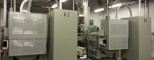
Emergency power comes from two 1,250-kW paralleled generators. The generator room and controls are set up to accommodate a third generator if future demand requires. A 6,000-amp emergency distribution switchboard services eight transfer switches, six of which are bypass isolation type, including two critical, two equipment, one life-safety and one non-essential emergency. A dedicated chiller transfer switch and the fire pump transfer switch are also served from the emergency distribution. A new 15,000-gallon above-ground double-wall fuel oil storage tank is dedicated for generator use.
Power monitoring
In conjunction with the new equipment, a complete metering and control system was specified to allow the hospital to keep track of the entire distribution from the central office. All of the main circuit breakers and distribution breakers in the main normal and emergency switchboards have monitoring devices. With just the click of a mouse, the hospital can access information on any branch, including voltage, current, kW, power factor, THD and other useful data. Additionally, the system will warn the hospital when the electrical system becomes unstable. Alarm points for under-voltage and over-voltage, voltage and current phase unbalance are just a few of the alarms hospital staff can receive and respond to, if necessary.
Boiler crunch
The hospital’s original boiler room was barely 37-ft. x 39-ft., yet housed two 10,041-MBh boilers flanking one 16,736-MBh boiler. To appreciate the close quarters, one only had to stand between two boilers and touch them with outstretched arms. One wall was composed largely of louvers to accommodate boiler removal and combustion/ventilation air. This wall was removed and the roof structurally reinforced to open to the expansion area. The new boiler room became an 85-ft. x 39-ft. space to house the existing 500-bhp boiler and two new 300-bhp Superior fire-tube boilers. All boilers are dual-fuel (natural gas, No. 2 fuel oil) capable.
Continuous operation of the steam system was essential because it provided sterilization for medical tools, produced domestic hot water and was the source for space heating and reheat necessary for humidity control. Redundancy was equally important to maintain a comfortable environment. As the two older boilers were removed to make way for a new condensate receiver (surge tank) and dearator system and the two new boilers were installed in the expansion area, a temporary trailer-mounted boiler was tied into the hospital’s steam main at an existing valved connection that bypassed the central plant main header. The facility staff had established this connection before the last boiler replacement in 1984. The temporary boiler provided redundancy and flexibility while the contractors wrestled with re-fit of the steam system, and the hospital’s plant operations staff sought reliable service. The temporary boiler was removed approximately five months later after refurbishment of the 500-bhp boiler was completed.
Piping problems
Work was complicated by the need to install chilled water, domestic cold water and other piping through the boiler room to a future sub-tunnel. These large, heavy pipes could not be supported by the boiler room’s aged roof structure, so steel posts and support structures were installed. The team took great care in placing the posts and support structures so they did not impede access to the new equipment. Once the new emergency generators were on-line, the existing generators were removed to create an expanded chiller room housing two new 600-ton centrifugal chillers equipped with variable frequency drives (VFDs) for enhanced partial load efficiency.
Re-piping of the entire chiller plant began as winter approached. Temporary pipe hoses and electric power were configured to provide circulation and nominal cooling in case the weather did not cooperate. One 400-ton and two 225-ton centrifugal chillers were removed and a new primary-secondary pumping system replaced the constant-volume pumping setup. Two distinct distribution loops were established for more efficient pumping energy use. A standby secondary pump with control valves is configured for automatic pump changeover by the direct-digitally control building automation system. A 600-ton centrifugal chiller was re-used and remained in place throughout the process.
Load lowdown
Cooling load projections for the completed expansion project were estimated at 1,084 tons. Thus, the plant is set to operate with two chillers and have a redundant third chiller available. Space for a future chiller is defined should future load dictate. A new two-cell, 1,200-ton cooling tower equipped with VFD fan motors was installed on the central plant roof, replacing older 400-ton and 225-ton units. Each cell can work independently. A two-cell, 800-ton cooling tower previously retrofit for VFD fan motors was re-used. A new plate frame in parallel with the chillers’ heat exchanger provides chilled waterside free cooling when ambient conditions allow.
Do you have experience and expertise with the topics mentioned in this content? You should consider contributing to our CFE Media editorial team and getting the recognition you and your company deserve. Click here to start this process.


